
Simple but reliable car battery tester

The car battery tester circuit based on the LM3914 IC is designed to provide a visual representation of the battery's voltage level. The LM3914 is a bar graph/LED dot display driver that can drive up to ten LEDs in either a bar graph or dot mode, making it an ideal choice for indicating battery voltage levels.
To construct the circuit, the LM3914 is connected to a series of LEDs, which will light up according to the voltage level of the battery being tested. The circuit requires minimal components, including resistors for current limiting and a power supply that can range from 4.5V to 12V, which aligns well with standard automotive battery voltages.
The input voltage is applied to the LM3914, which translates the analog voltage into a corresponding number of lit LEDs. For instance, a fully charged car battery typically shows around 12.6V to 12.8V, while a battery in a discharged state may drop below 12V. The circuit can be calibrated to provide accurate readings by adjusting the reference voltage and using appropriate resistor values.
This battery tester is particularly beneficial for automotive applications, providing quick and reliable voltage readings to help diagnose battery health and performance. The simplicity of the circuit, combined with the availability of the LM3914, makes it an excellent project for both amateur and professional electronics enthusiasts.Simple but reliable car battery tester Circuit diagram This circuit uses the popular and easy to find LM3914 IC. This IC is very simple to drive, needs no voltage regulators (it has a built in voltage regulator) and can be powered from almo..
🔗 External reference
Related Circuits
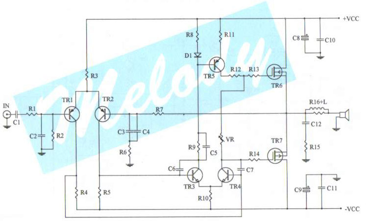
The schematic diagram of a 100-watt audio amplifier utilizing MOSFET technology. A comprehensive collection of electronic circuit diagrams is available, including a 100W RMS amplifier and a 0-30V stabilized variable power supply with current control. The 100-watt audio amplifier schematic...
This involves controlling servo motors through software programming using the PIC 16C71 microcontroller. The input signals range from 0 to 5V. The circuit utilizes the PIC 16C71 microcontroller, which is an 8-bit device suitable for controlling servo motors. The microcontroller...
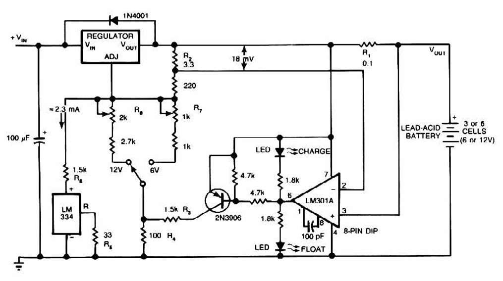
The schematic for this charger is straightforward. It is designed to charge a Gel Cell or other lead-acid types. This simple battery level monitor circuit can indicate the charging process in a 12 Volt lead-acid battery or tubular battery....
The circuit utilizes a CMOS dual D flip-flop (CD4013) to toggle a relay or other load using a momentary push button. Multiple push buttons can be connected in parallel to control the relay from various locations. A high signal...
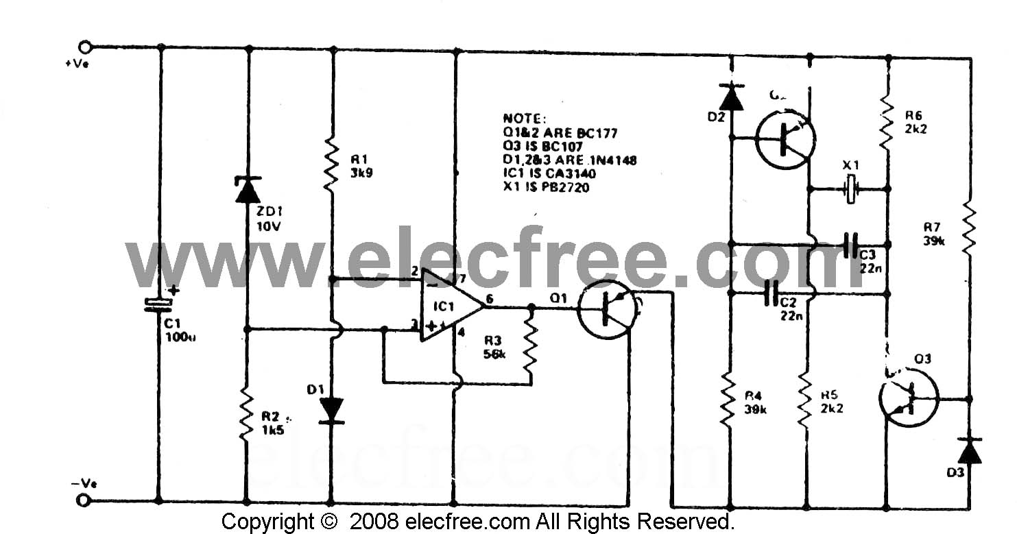
To check the battery in a car, an easy circuit utilizing the IC CA3140 and a transistor is employed. The voltage level of an automobile battery is influenced by many factors, and if it is high... The circuit for checking...
Many later radios utilize four 7-pin valves and require a high tension (HT) supply of 90V at approximately 12mA, and a low tension (LT) supply of either 125mA or 250mA, depending on the specific valves used. The original batteries...