
Battery Powered Soldering Iron PCB

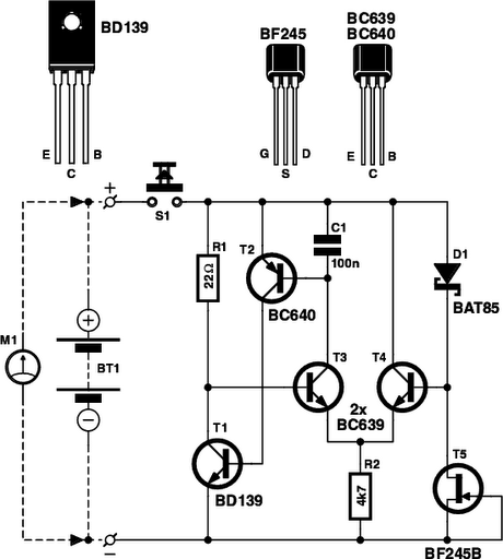
The inverter circuit designed for soldering iron applications addresses the limitations of conventional soldering methods that rely on mains electricity. The astable multivibrator configuration formed by the BC547 transistors (T1 and T2) is crucial for generating a consistent 50Hz square wave signal. This frequency is suitable for the operation of the transformer and the subsequent heating of the soldering iron.
The PNP Darlington stage, consisting of transistors T3 through T6, amplifies the signal from the astable multivibrator, ensuring that sufficient current is available to drive the power transistors. The choice of BC558 and BD140 in the Darlington configuration allows for high current gain, which is essential for efficient operation.
The push-pull arrangement of the 2N3055 transistors is particularly effective for driving the transformer X1. This configuration allows for efficient switching and minimizes power loss, making the circuit suitable for battery operation. The transformer is designed to step up the voltage to 230V AC, which is necessary for heating the soldering iron effectively.
The 12 Volt 7Ah battery provides the necessary power for the entire circuit. The selection of this battery capacity ensures a reasonable operating time, although the actual duration will vary based on the power rating of the soldering iron used. The circuit's design allows for portability and convenience, making it an excellent solution for fieldwork or situations where mains power is unavailable.
In summary, this inverter circuit provides a practical and efficient means of operating standard soldering irons away from mains electricity, utilizing a well-structured arrangement of transistors and passive components to achieve the desired outcome.As we know, traditional soldering irons uses mains ac supply to get heated but this will be annoying when we want to use it in the absence of mains supply. Here is a simple inexpensive circuit which we can call it as a inverter for normal soldering iron (25W, 30W, 35W).
The circuit can drive the soldering iron in the absence of power supply from m ains. This cold soldering iron circuit uses eight transistors and few resistors and capacitors. The battery should be a 12 Volt 7Ah. Each BC547 transitors - T1 and T2 form an astable multivibrator that produces 50Hz signal. The output of it drives the pnp darlington driver stage transistors formed by transistors T3-T5 and T6 utilizing BC558 and BD140. Two 2N3055 power transistors will perform push-pull operation whose output drives the transformer X1 which drives the soldering iron.
When you power the circuit using switch S1, transformer X1 produces 230V AC at its primary terminal. This voltage can be used to heat your soldering iron. The battery backup will depend upon the power rating of the iron. 🔗 External reference
Related Circuits
Motorcycle battery charger power supply. Refer to the mentioned page for an explanation of the power supply related circuit diagram. The description of the battery charger indicator: The circuit above enhances the appearance of a simple battery charger, making...
Is the battery empty, or is there something wrong with the device? This question can be challenging when a battery-powered device, such as a Walkman, appears to be non-functional upon switching it on. Before seeking professional servicing, the initial...
Battery discharge leads to plate acidification, negatively impacting the battery's lifespan. To address this issue, a specialized micro-power battery over-discharge protection circuit has been designed. The circuit features a very low detection current (1.1 mA). Once the protection circuit...
A simple NiCd charger can be constructed using commonly available components and an inexpensive LM317 or 78xx voltage regulator. It incorporates a current limiter made up of resistor R3 and a transistor, allowing it to charge multiple cells until...
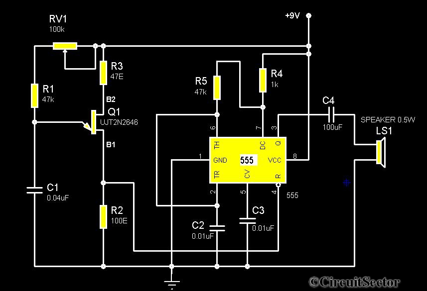
The circuit diagram illustrates a timer 555-based rain sound generator. It requires a 9V DC power supply, which can be provided by a 9V battery. The circuit utilizes a 0.5W, 8-ohm speaker to produce sound. When powered by a...
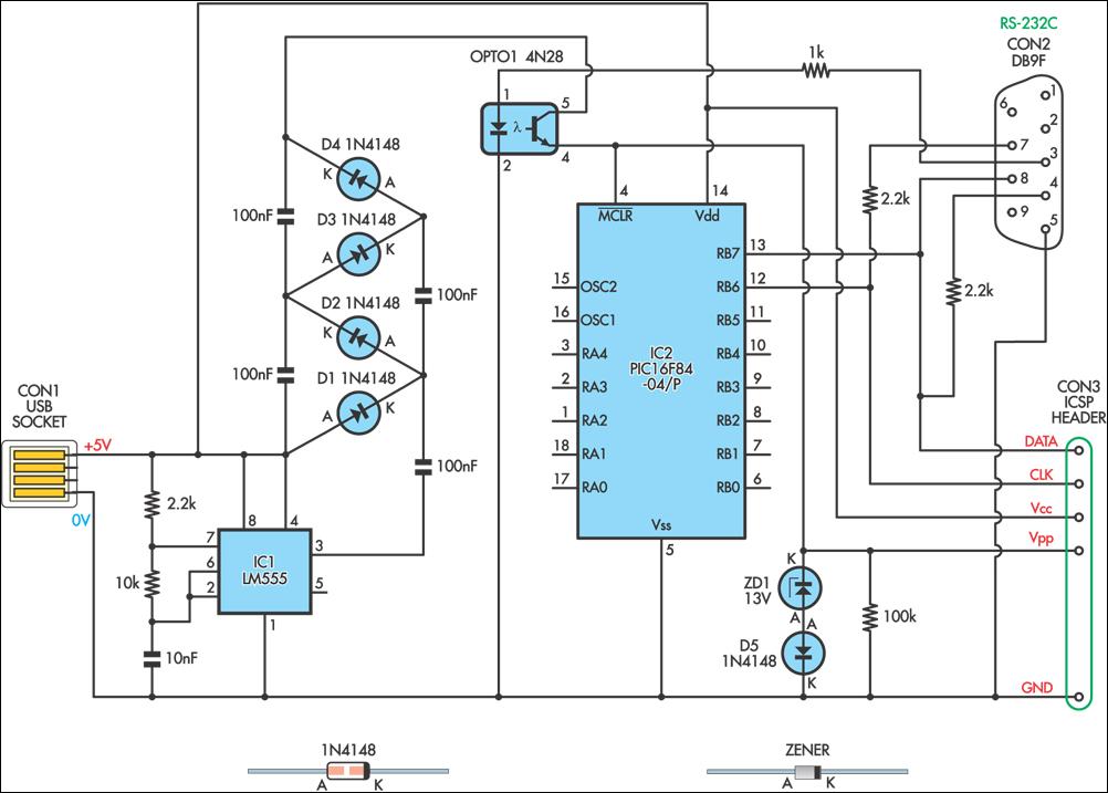
This simple circuit can be used to program the PIC16F84 and similar "flash memory" type parts. It utilizes a 555 timer IC to generate the programming voltage from a +5V rail, allowing the circuit to be powered from a...