
USB-Powered PIC Programmer

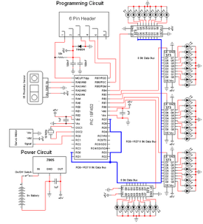
The circuit design for programming the PIC16F84 microcontroller is centered around a 555 timer IC, which serves as an oscillator to generate the necessary programming voltage. The 555 timer operates in astable mode, producing a square wave output at a frequency of approximately 6.5 kHz. This frequency is suitable for driving the subsequent components of the circuit effectively.
The output from the 555 timer is connected to a voltage multiplier stage, which consists of four 100nF capacitors and 1N4148 diodes arranged in a Cockcroft-Walton configuration. This configuration allows for the generation of a higher voltage from the 5V supply provided by a USB port. The capacitors charge and discharge in a manner that effectively steps up the voltage, making it suitable for programming the microcontroller.
During the programming process, the output from the voltage multiplier is routed to the MCLR/Vpp pin of the PIC microcontroller through a 4N28 optocoupler. The optocoupler serves to isolate the microcontroller from the timing circuit, enhancing the safety and reliability of the programming operation. When the optocoupler is activated, it allows the higher voltage from the multiplier to reach the MCLR/Vpp pin, enabling the programming mode.
To prevent damage to the microcontroller, diodes ZD1 and D5 are included in the circuit to clamp the output voltage to approximately 13.6V. This ensures that the maximum allowable input voltage (Vihh) for the PIC is not exceeded, protecting the device from potential over-voltage conditions. Additionally, a 100kΩ pull-down resistor is connected to the MCLR/Vpp pin. This resistor ensures that the pin is held at a valid logic low level (Vil) when the optocoupler is not conducting, preventing unintended programming or activation of the microcontroller.
The design is compatible with the JDM programmer standard, which is widely used for programming various microcontrollers. This compatibility allows the circuit to be integrated with software like ICProg, making it a versatile solution for programming flash memory microcontrollers in various applications.This simple circuit can be used to program the PIC16F84 and similar "flash memory" type parts. It uses a cheap 555 timer IC to generate the programming voltage from a +5V rail, allowing the circuit to be powered from a computer`s USB port. The 555 timer (IC1) is configured as a free-running oscillator, with a frequency of about 6. 5kHz. The output of the timer drives four 100nF capacitors and 1N4148 diodes wir-ed in a Cockroft-Walton voltage multiplier configuration. The output of the multiplier is switched through to the MCLR/Vpp pin of the PIC during programming via a 4N28 optocoupler.
Diodes ZD1 and D5 between the MCLR/Vpp pin and ground clamp the output of the multiplier to about 13. 6V, ensuring that the maximum input voltage (Vihh) of the PIC is not exceeded. A 100k © resistor pulls the pin down to a valid logic low level (Vil) when the optocoupler is not conducting.
The circuit is compatible with the popular "JDM" programmer, so can be used with supporting software such as "ICProg" (see ). 🔗 External reference
Related Circuits
The personal radar system utilizes the PIC microcontroller PIC18F452 as a hobby project. The attached circuit diagram of the radar may appear simple; however, careful analysis of the PIC18F452 radar circuit is necessary to prevent damage. This personal radar...

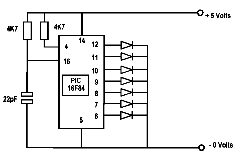
A simple program that will blink an LED. All that is required is a basic JDM programmer, and the setup is ready to go. The circuit requires a power supply, and while a good power generator is recommended, a...
Several years ago, a colleague suggested the use of PICs for hobby projects, specifically amateur television. Extensive time was spent developing and experimenting with video mixers, faders, and effects units using analog and digital circuits (TTL gates), which often...

It was discovered through experience why the 6V EQ-5 hand controller should not be connected to 12V by mistake. It only took about half a second to damage the hand controller. Upon inspection, it became clear that the large...

A PIC16x84 processor can be utilized to generate a PSK31 or FSK31 signal. This signal may serve various purposes, including beacon transmissions, telemetry, experimentation, or QSOs, though the latter may involve some quirks. The PSK transmitter was initially designed...
The circuit diagram is shown to the right. A larger or PostScript version is available if preferred. The design centers around a Microchip PIC16F628A microcontroller, which is currently available for less than one pound from various suppliers, including Crownhill...