
SciTech PS-3R Power Supply Circuit

The SciTech PS-3R Power Supply Circuit is designed to provide a stable DC output of 13.8 volts, suitable for various electronic applications, particularly in powering devices that require regulated voltage. The power supply is capable of delivering a surge current of up to 5 Amps, which is beneficial for starting devices that may draw higher current momentarily. Under normal operating conditions, the circuit maintains a constant output current of 3 Amps, ensuring reliable performance for connected loads.
The circuit typically consists of a transformer, which steps down the AC voltage from the mains supply to a lower AC voltage. This AC voltage is then rectified using diodes to convert it into pulsating DC. A smoothing capacitor is used to filter the pulsating DC, providing a more stable output. The inclusion of a voltage regulator ensures that the output remains steady at 13.8V, even when the load varies.
Transistors within the circuit may be utilized for switching and amplification purposes, depending on the specific design requirements. Additional components such as resistors, capacitors, and possibly inductors may also be included to enhance performance, improve stability, and filter out noise.
Overall, the SciTech PS-3R Power Supply Circuit is engineered to deliver reliable power with specific features tailored for efficient operation in various electronic applications.The following circuit shows about SciTech PS-3R Power Supply Circuit. Features: 13.8vDC, 5 Amps Surge, 3 Amps Constant. Component: Transistor, .. 🔗 External reference
Related Circuits
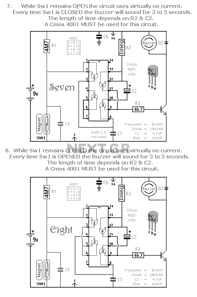
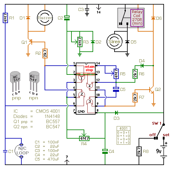
A selection of small self-contained CMOS alarm circuits is presented. The main features of each alarm are indicated on the circuit diagram itself. All circuits exhibit a very low standby current, making them suitable for battery operation. Each pair...
This document describes a 100 Watt inverter circuit that utilizes a minimal number of components. The circuit employs the CD 4047 integrated circuit (IC) from Texas Instruments to generate 100 Hz pulses, along with four 2N3055 transistors that drive...
The internal disconnection circuit for a blanket operates on the principle of induction. It includes a wire approximately 2 cm in length that senses the proximity of a charged mains power source. When the sensing wire is close to...
The circuit was originally available in kit form from a surplus supplier, but it is likely more widely accessible now. It introduces innovative concepts such as utilizing a 555 timer as a pulse width modulator (PWM) and employing serial/parallel...
This is a single-zone alarm system featuring independently adjustable Exit, Entry, and Siren Cut-Off timers. It is designed to accommodate standard normally-closed input devices, such as magnetic reed contacts, foil tape, and passive infrared sensors (PIRs). The system can...

Also known as a no-shot multivibrator, this circuit is often utilized as a pulse (square wave) signal source. The astable flip-flop functions as a strong positive feedback amplifier, with its two branches coupled by an RC timing circuit, resulting...