
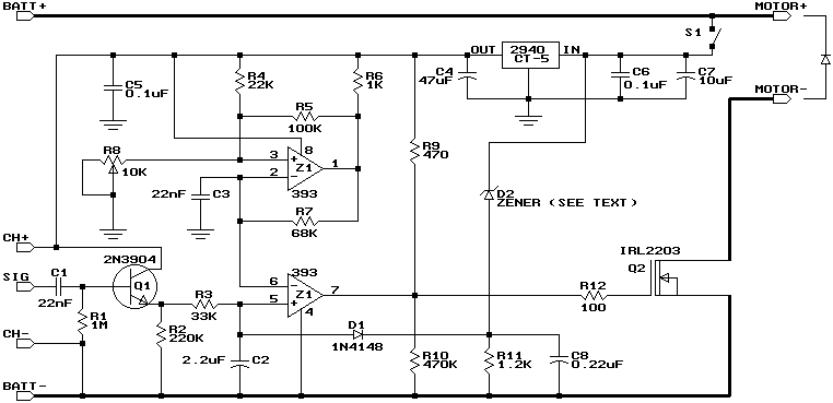
Battery voltage indication circuit

This battery voltage indication circuit is designed to monitor the voltage level of a battery and provide a visual alert through an LED indicator. The circuit typically consists of a voltage divider network, a comparator, a transistor, and an LED.
The voltage divider is formed by two resistors connected in series across the battery terminals. This divider reduces the battery voltage to a level suitable for comparison. The output from the voltage divider is fed into a comparator, which is configured to compare the divided voltage against a predetermined reference voltage. This reference voltage is set to correspond to the critical battery voltage level.
When the battery voltage is above the critical threshold, the output of the comparator remains high, keeping the transistor in the off state. Consequently, the LED remains unlit, indicating that the battery voltage is normal. Conversely, when the battery voltage drops below the critical level, the comparator's output switches low, turning on the transistor. This action allows current to flow through the LED, which then begins to flash, signaling that the battery is low and requires attention.
The flashing behavior of the LED can be achieved by incorporating additional components, such as a capacitor and a resistor, to create a timing circuit that controls the on-off cycling of the LED. This feature enhances the visibility of the low battery condition, making it more noticeable to the user.
Overall, this circuit provides a simple yet effective method for monitoring battery voltage and ensuring timely awareness of low battery conditions through visual signaling. Battery voltage indication circuit Using this circuit can change the status display, if foot plus a further transistor drive LED, the battery voltage is normal. LED is not lit, and when the battery voltage falls below a critical value, LED begins to flash indicating that the circuit shown
Related Circuits
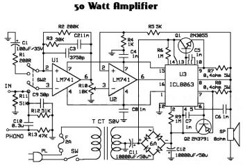
An audio amplifier is an electronic device designed to amplify low-power audio signals, which primarily consist of frequencies ranging from 20 Hz to 20,000 Hz, the human range of hearing. This amplification is necessary to drive loudspeakers and represents...
This design is based on one published by Milan Lulic in the German magazine elektroModell. Mr. Lulic's design is for surface mount technology (SMT) construction, whereas mine uses standard off-the-shelf components, and is therefore better suited to construction by...

An issue with CPLD and FPGA devices is that they have numerous I/O pins, resulting in schematics that quickly become overwhelmingly large. Different sections of the schematic have been partitioned to illustrate the motor control circuit, analog-to-digital converter circuit,...
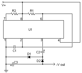
This simple circuit is a good solution to the powering a dual supply op amp from a single battery problem. The circuit simply takes a positive voltage and inverts it. It uses only one 555 timer and a few...
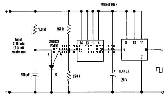
A direct current (DC) voltage source within the range of 2 to 15 volts can be converted into a unipolar square wave. This square wave has a peak amplitude that is nearly equal to the DC source voltage, with...
The circuit for the power amplifier has a power output of up to 1500W RMS and is commonly utilized in outdoor sound systems. The final image displays a series of power amplifiers that utilize 10 sets of power transistors....