
Baxandall Tone Control Circuits Using Two Transistor

The tone control circuit based on the Baxandall configuration is designed to enhance audio signals by providing adjustable bass and treble controls. The circuit typically includes two stages of amplification using bipolar junction transistors (BJTs), which are selected for their suitability in audio applications due to their low noise and high gain characteristics.
In the Baxandall design, the first transistor serves as the input stage, where the audio signal is fed in. The gain of this stage is adjustable via a potentiometer, allowing for fine-tuning of the input signal level. The output of the first transistor is then connected to the second transistor, which further amplifies the signal. This configuration allows for a smooth transition between boosting and cutting frequencies, providing a user-friendly interface for sound customization.
The circuit requires a DC power supply within the range of 9 to 15V, which is typical for low-power audio applications. The choice of transistors is critical; general-purpose audio transistors, such as the BC547 or 2N3904, are recommended due to their favorable characteristics for audio signal processing. These components are widely available and cost-effective, making the circuit accessible for both hobbyists and professional applications.
Passive components such as resistors and capacitors are also integral to the design. The values of these components are selected to define the frequency response of the circuit, allowing for specific adjustments to bass and treble levels. Overall, the Baxandall tone control circuit is a versatile and efficient solution for enhancing audio quality in various electronic devices.This is design circuit of tone control circuit that is use very popular Baxandall configuration, a simple circuit configuration that provides boost and cut control in continuous manner. This circuit is very cheap to build, and it`s commonly implemented in commercial product. This circuit is built by two transistors. This is the figure of the schem atic. The transistors can be substituted by any general audio transistors with small current gain more than 100 (BC547, 2N3904, and many more). The supply voltage for this circuit is 9-15V DC. The components that is used is low cost and can buy in component electronics store. 🔗 External reference
Related Circuits
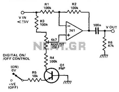
When transistor Q1 is switched off, the circuit operates as a voltage follower. By applying a positive voltage to the emitter of Q1 through a 10 kΩ resistor, the transistor is activated and enters saturation. Consequently, the lower end...

This is a simple hobby circuit for a remote-controlled toy car. The primary component utilized is the IR sensor circuit, which includes a TSOP IR receiver. This receiver allows the user to start and stop the DC motor of...
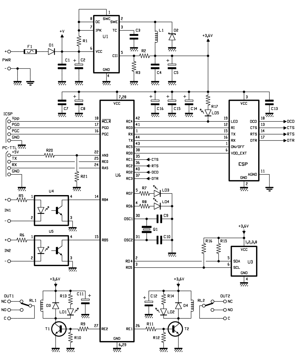
Connected to a burglar alarm or fire alarm, this device facilitates phone calls that play voice messages. It is controlled via DTMF actuators, allowing for immediate operation. In recent years, several telecontrols based on the SIM900 GSM module have...
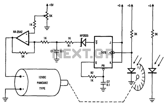
The system comprises the HA-2542 operational amplifier, a compact 12 V DC motor, and a position encoder. During operation, the encoder generates a series of constant-width pulses that charge capacitor C1. These integrated pulses create a reference voltage proportional...
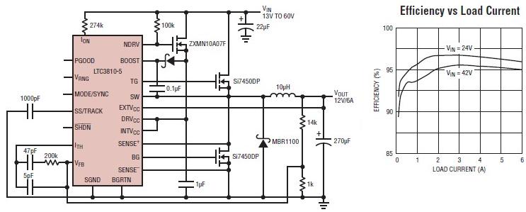
The LTC3810-5 synchronous step-down switching regulator controller allows for the design of a straightforward 12-volt switching power supply electronic project with minimal external components. This controller can directly reduce voltages from up to 60V, making it suitable for telecommunications...
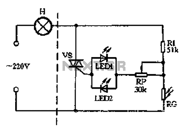
The circuit section includes a photoresistor (RG) and a fixed resistor (Rl) that form a voltage divider. Light-emitting diodes (LED1 and LED2) serve a dual purpose as power indicators and trigger rectifiers. During the positive half-cycle of the alternating...