
BC548 Heat Sensor Diagram Circuit

The heat sensor circuit operates on the principle of temperature-dependent resistance changes in the thermistor. The NTC thermistor is critical in this design, as it allows for the detection of temperature variations. As the ambient temperature rises, the decrease in thermistor resistance leads to an increase in current through the potential divider, resulting in a higher voltage at the junction of the thermistor and resistor. This voltage is crucial for controlling the transistor.
The BC548 NPN transistor serves as a switching element in the circuit. The base resistor of 3.3 kΩ limits the current into the base of the transistor, ensuring that it operates within safe parameters. The use of a Zener diode for the emitter stabilizes the voltage, providing a reliable reference for the base-emitter junction. When the input voltage at the base exceeds 4.7 volts, the transistor enters saturation, allowing current to flow from the collector to the emitter, thus activating the buzzer.
This circuit is versatile and can be adapted for various applications, such as temperature alarms, automatic fans, or other devices that require temperature monitoring and control. The design is straightforward and can be implemented with minimal components, making it suitable for educational projects or practical applications in temperature-sensitive environments.Heat sensor circuit can be used to control any device using heat sensor. In this circuit a thermistor and a resistance is connected in series. This arrangement makes a potential divider circuit. Here the thermistor is Negative Temperature Coefficient type. So when the room temperature is increased its resistance decreases simultaneously and more c urrent flows through the resistor and the thermistor. We find more voltage at the junction of the resistor and the thermistor. Our thermistor resistance value is 110 ohms. Suppose the resistance value becomes 90 ohms after heating the 110 ohms thermistor. Then the voltage across one resistor of the voltage divider circuit equals the ratio of that resistor`s value and the sum of resistances of the voltage across the series combination. This is the concept of voltage divider. The final output voltage of the voltage divider circuit is now applied to the npn transistor (BC548) through the base resistor (3.
3K ohms). Here the emitter resistor is replaced with a zener diode. Emitter voltage is maintained at 4. 7volt with the help of zener diode. This voltage is used to compare voltage. Transistor conducts when base voltage is greater than the emitter voltage. Transistor conducts if it gets more than 4. 7volt of base voltage. Then the circuit is completed through buzzer and it gives sound. 🔗 External reference
Related Circuits
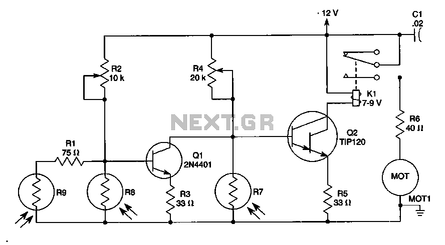
The sun trucker employs three photoresistors, R7, R8, and R9, to enable the circuit to track the sun during daylight hours while ceasing operation at night. Additionally, the circuit can be duplicated to achieve movement along four axes by...
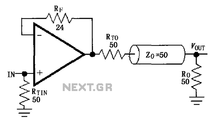
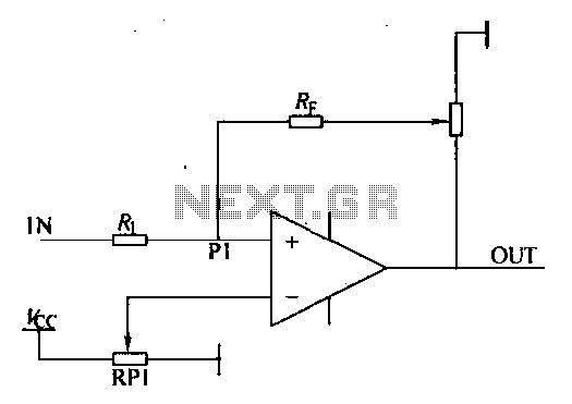
The MAX4450/4451 unity gain line is illustrated in the driving circuit. The MAX4450/4451 features internal compensation, a 24-ohm resistor in series within a feedback loop, along with capacitors and inductors that can reduce the Q value of the feedback...
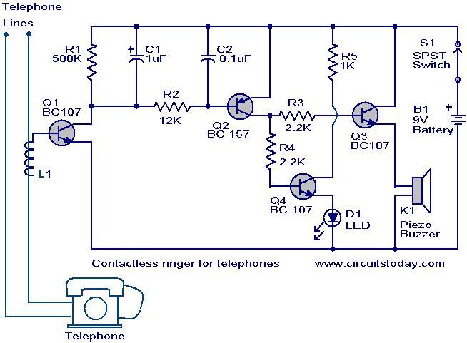
The contactless telephone ringer circuit is designed to produce an audible ring and a visual indication when a call is received. Its primary advantage lies in the absence of direct contact between the telephone line and the circuit, which...
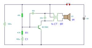
The simple bell circuit without IC. It includes a doorbell circuit that can produce different sounds using integrated circuits, transistors, and resistors. The circuit utilizes a coded trigger mechanism to differentiate between various visitors. When the button is pressed,...
An automatic humidifier can be utilized for humidity control in households, hatcheries, poultry farms, or juvenile poultry houses. When the humidity level falls below 50%, the automatic humidifier activates to maintain a specific humidity level that is beneficial for...
Environmental interference can affect the transfer switching, leading to the production of burrs in confidence disgrace. The switch position signal will control the computer system with the reliability of lanthanum burrs. The work has some impact. Glitches are typically...