
2 Axis Solar Tracker Circuit

The sun trucker circuit is designed to harness solar energy effectively by utilizing a photoresistor-based tracking mechanism. The three photoresistors, R7, R8, and R9, are strategically placed to detect the intensity of sunlight from different angles. This arrangement allows the circuit to determine the direction of the sun's position in the sky.
When the sun's light hits the photoresistors, the resistance changes, generating a variable voltage output that can be read by a microcontroller or comparator circuit. The microcontroller processes the readings from the photoresistors and determines which direction the motors should move to align the solar panel with the sun. This alignment optimizes the panel's exposure to sunlight, thereby maximizing energy collection.
To enhance the system's capabilities, the circuit can be duplicated, allowing for movement along four axes. This is achieved by incorporating two motors, each responsible for controlling the movement in a specific axis. The first motor can control the azimuthal movement (left and right), while the second motor can handle the elevation (up and down) of the solar panel.
The circuit should also include a light-dependent resistor (LDR) or a similar mechanism to detect low light levels, which will trigger the motors to stop their operation at night. This feature is essential to prevent unnecessary wear on the motors and to ensure energy efficiency.
In summary, the sun trucker circuit is a sophisticated system that utilizes photoresistors for solar tracking and can be expanded for multi-axis movement through the addition of motors, making it an effective solution for maximizing solar energy capture.The sun trucker uses a combination of three photoresistors R7, R8 and R9, to ensure that the circuit will follow the sun during the day, but stop working at night time. Make this circuit 2 times to have 4 Axis move, by using 2 motors.
Related Circuits
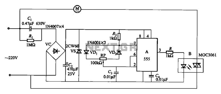
The circuit depicted in Figure 3-9 shares similarities with Figure 3-8, with the distinction that the zero-off MOC3061 type photoelectric coupler is directly connected to control the operation of the fan. The circuit utilizes the MOC3061, a phototransistor optoisolator, which...

A 1W stereo headphone amplifier circuit, based on the TDA2822, is designed for portable players, radios, and other electronic devices that utilize headphones as the output. The TDA2822 is a dual audio power amplifier IC capable of delivering up to...

A replication of the Afrotechmods laser tripwire circuit utilizing a simple laser pointer, an IRF244 MOSFET (most NPN transistors would also suffice), a few resistors, and one light-dependent resistor (LDR). The Afrotechmods laser tripwire circuit is an innovative application of...
A touch switch is a switch that is turned on and off by touching a wire contact, instead of flicking a lever like a regular switch. Touch switches have no mechanical parts to wear out, so they last a...
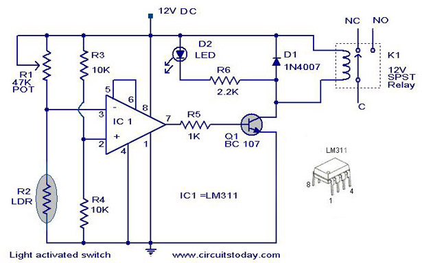
A simple light-activated switch circuit diagram utilizes the National Semiconductor comparator IC LM311 and a light-dependent resistor (LDR). The circuit functions as a voltage comparator, with the non-inverting input of IC1 receiving a reference voltage of 6V through resistors...
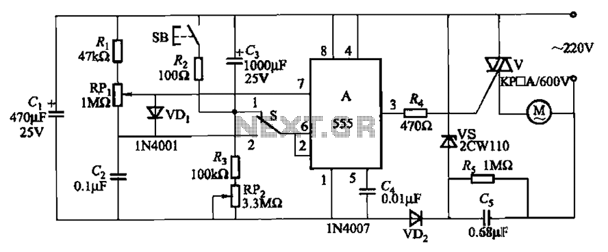
The circuit illustrated in Figure 3-12 incorporates variable speed and timing control functions. When switch S is set to position 1 and button SB is pressed, the motor initiates operation. After a predetermined delay, the motor automatically shuts down....