
Temperature controller circuit

The operation of the circuit begins with the application of AC 220V voltage to the transformer (T), which is rectified by UR1 and filtered by capacitor C1 to produce a stable +12V supply for the humidity control circuit. A light-emitting diode (LED) indicates the operation status. The voltage is then adjusted using a resistor (R1) and a Zener diode (VS1) to create a flat-topped AC waveform. The sampling resistor (RP1) adjusts the input signal, while the humidity sensor (RS) converts humidity changes into a varying resistance. As humidity increases, the resistance of RS decreases, allowing more current to flow through the ammeter (PA). When humidity is low, the current is minimal, causing the voltage at the inverting input of IC2 to drop below the reference voltage at the positive input. This results in a high output from IC2, turning on the transistor (VT) and activating the relay (K), which powers the humidifier. As humidity rises and the resistance of RS increases, the inverting input voltage rises. When the humidity reaches the set point, the inverting input voltage exceeds the positive input voltage, causing IC2 to output a low signal, deactivating the transistor (VT) and releasing the relay (K), thereby cutting off power to the humidifier. This feedback mechanism allows the device to maintain humidity levels within a predetermined range effectively. Automatic Humidifier can be used to control humidity control family, it can also be used hatchery poultry farms or juvenile poultry house climate control. When the humidity is less than 50%, enabling automatic humidifier work To maintain a certain humidity environment, human and animal health alike. (1) circuit automatically controlled humidifier circuit from the power circuit, humidity testing, indicating the circuit and humidity control circuit, as shown in FIG.
Power circuit from the power transformer T, rectifier bridge UR1, filter capacitors cl, C2, most resistance, light-emitting diodes I. ED and three-terminal voltage regulator integrated circuit ICl (LM7812) components. Humidity detection and indication circuit from the power transformer T Buck 8V, resistance ~ Shu Shu, VSI and Zener diode VS2, potentiometer RP1, humidity resistance RS, rectifier bridge UR2, capacitors C3 and C4 and ammeter PA components.
Humidity control circuit consists of an operational amplifier lC2 (FLA741), hurricane resistance -R, with horses, diode VD1 and VD2, transistor VT and relay electrical composition K. (2) analysis of the circuit works the way AC 220V voltage by T Buck, UR1 rectifier, cl filtering and stability after 1C1 Henan, generating + 12V voltage supply humidity control circuit, while light VL T} another pass the buck, Ri and while limiting and VS1, vsz regulators, cut into flat-topped wave AC voltage.
This alternating voltage RP1 adjust the sampling, RS buck and UR2 rectified into DC voltage, and then by C3, R. After crossing the limiting filter and C, was added to the ammeter PA. RS Yun resistance varies with changes in humidity. The higher the humidity. RS resistance more small DC current flowing through the PA will be. When humidity is low, the current flowing through R is small, sleepy IC2 inverting input terminal voltage is lower than the positive input of the reference voltage and outputs a high level, so that VT conduction.
K pull its normally open contact connected, so that the humidifier power work. With increasing air humidity, RS resistance began to increase by Gan, IC2 inverting input voltage rise. When the humidity reaches of no humidity, IC2 due to the inverting input voltage is higher than its positive input voltage and output low, the VT end, K release, and its normally open contact humidifier power supply cut off.
And so forth to work, you can control the humidity of the environment within a set range of humidity.
Related Circuits
The objective is to enhance information transmission through the use of articles. Please contact us via email at [email protected] within 15 days if there are any issues related to article content, copyright, or other concerns. Prompt action will be...
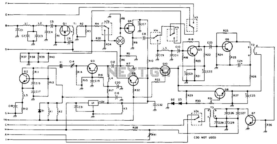
This 49-MHz FM transmitter comprises an audio amplifier, a low-pass filter, three RF stages, and a regulated DC power supply. The output power is approximately 16 mW into a 50-ohm load. This transmitter is suitable for various 49-MHz applications,...
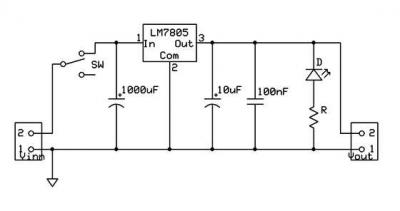
A micro power supply unit (PSU) is designed to power a breadboard with a voltage output of 5 volts. It can be connected to a 9V battery, a 12V source, or any other direct current (DC) power supply ranging...
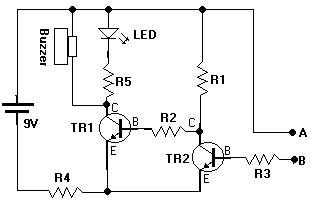
This document presents a water sensor circuit designed to monitor soil moisture levels for plants. This circuit is straightforward and is constructed using five resistors, two transistors, an LED, a buzzer, and a battery. The operation of the circuit...
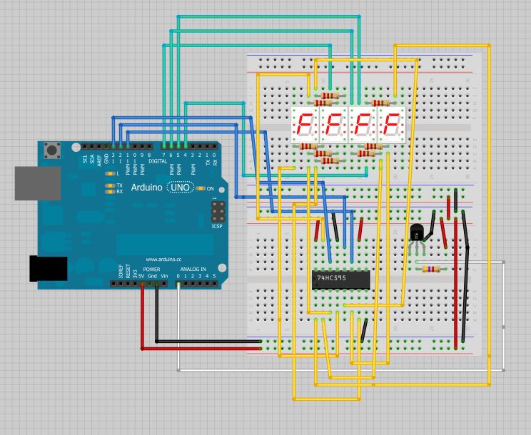
The intention is to utilize this code in future projects involving 7-segment displays. For those interested in learning more about 7-segment displays, additional information can be found in a related post. 7-segment displays are widely used in electronic devices for...
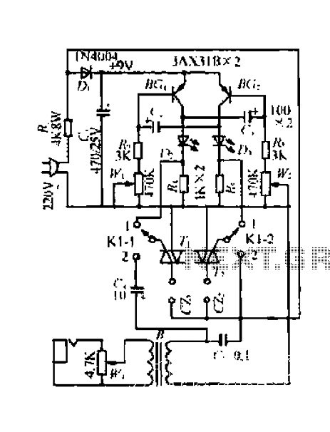
A 220V mains power supply is reduced using a control circuit designed by N. Guanidine D. Yi. The circuit features a spike Bode and provides a +9V voltage supply. It includes components such as a control port (G), a...