
Bcd-to-analog converter

The circuit operates by accepting a four-bit BCD input, which corresponds to decimal values ranging from 0 to 9. The SN74141 is designed to control multiple outputs, each representing a specific voltage level. When a particular BCD code is received, the corresponding output of the SN74141 is activated, grounding the appropriate point in the voltage divider network. This action allows the voltage divider to produce a precise output voltage that matches the decimal value indicated by the BCD input.
The voltage divider consists of a series of resistors that are arranged to provide specific voltage levels at their junctions. The values of these resistors are critical, as they determine the output voltage for each BCD input. The accuracy of the output voltage is contingent upon the tolerance of these resistors; hence, using resistors with low tolerance is advisable for improved precision. Furthermore, a stable reference voltage source is essential for maintaining consistent output voltages across different operating conditions.
To enhance accuracy, the circuit can incorporate adjustable preset resistors within the divider chain. These presets allow for fine-tuning of the output voltages, compensating for any discrepancies caused by resistor tolerances or variations in the reference voltage. Calibration involves setting the presets to achieve the desired output voltage for each BCD input, ensuring that the circuit reliably produces the correct voltage levels.
The inclusion of the SN741 as a buffer serves to isolate the output of the voltage divider from the load, preventing any loading effects that could alter the output voltage. This buffer configuration ensures that the circuit can drive various loads without affecting the voltage levels generated by the divider.
Overall, this circuit provides a straightforward method for converting BCD inputs into corresponding variable voltages, with considerations for accuracy and calibration to ensure reliable performance in practical applications.This circuit will convert four-bit BCD into a variable voltage from 0-9 V in 1 V steps. The SN74141 is a Nixie driver, and has ten open-collector outputs. These are used to ground a selected point in the divider chain determined by the BCD code at the input, and so produce a corresponding voltage at the output. Accuracy of the circuit depends on the tolerance of the resistors and the accuracy of the reference voltage.
However, presets can be used in the divider chain, with correct calibration The 741 is used as a buffer.
Related Circuits
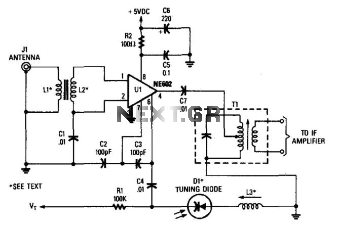
In this configuration, the NE602 serves as a frequency converter in a superheterodyne front-end setup. L1 and L2 form a broadband toroidal transformer, although a tuned transformer may also be utilized. The supply voltage ranges from +5 to +9...
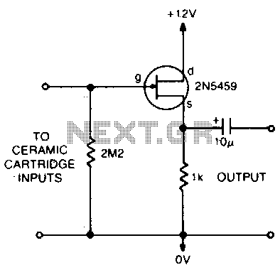
This circuit matches the very high impedance of ceramic cartridges, providing unity gain and low impedance output. By "loading" the cartridge with a 2.2MΩ input resistance, the cartridge characteristics are adjusted to closely compensate for the RIAA recording curve....
There are many individuals interested in listening to frequencies within the VHF range of 108 to 132 MHz. This VHF AM converter is designed to convert signals from a frequency band of 106 to 150 MHz, allowing users to...
A voltage-to-frequency converter (VFC) circuit is illustrated in the schematic diagram below. The circuit utilizes a 555 integrated circuit (IC) as the central component of its operation. The voltage-to-frequency converter (VFC) is a crucial electronic circuit that converts an input...
The VLF Converter is designed to receive signals for general coverage in shortwave receivers. It can pick up various unusual signals on frequencies below 15 kHz. This converter effectively transforms frequencies ranging from 0 to 250 kHz into a...
The circuit presented on this page attempts to be an interface to convert pulses such as provided by a Basic Stamp or R/C receiver to a dual PWM (Pulse Width Modulation) signal required by an H-bridge. The simplest circuit...