
Servo pulse to PWM converter

The described circuit functions as a pulse converter, transforming incoming pulses from devices such as a Basic Stamp or an R/C receiver into a dual PWM signal. This dual PWM output is essential for controlling the operation of an H-bridge, which is commonly used to drive DC motors in robotics and automation applications.
The design utilizes discrete components rather than a microcontroller, making it accessible for hobbyists and experimenters who may have these components readily available. The circuit typically includes resistors, capacitors, and possibly transistors or operational amplifiers to shape and modify the input signal into the desired PWM output.
In operation, the circuit receives the pulse signal from the Basic Stamp or R/C receiver. It processes these pulses by adjusting their width and frequency to create two separate PWM signals, which are then fed into the H-bridge. The H-bridge interprets these signals to control the direction and speed of the motor.
The choice of a traditional component-based approach over a microcontroller may also provide advantages in terms of simplicity and reliability, particularly in environments where programming may be less desirable or feasible. The total cost of the components is relatively low, comparable to that of a simple beverage, making it an economical solution for those looking to experiment with motor control without significant investment.
Overall, this circuit serves as a practical example of how traditional electronic components can be effectively utilized to achieve modern control applications.The circuit presented on this page attemps to be an interface to convert pulses such as provided by a Basic Stamp or R/C receiver to a dual PWM(Pulse Width Modulation) signal required by an H-bridge. The simplest circuit would use a small microcontroller like a PIC. This circuit takes a more traditional approach. Many experimenters will have all the parts already. Total parts cost should be equal to a simple espresso drink, although I have stopped drinking coffee I still remember how much it costs :-)
🔗 External reference
Related Circuits
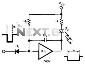
A single gate (open collector, non-inverting) generates a simple one-shot pulse that lasts for a duration equal to t, plus the RiCi time constant. R2 serves as a pull-up resistor to maintain the input of the gate high while...
When a GATE signal (between 3V and 15V) is applied, the capacitor C5 functions as a differentiator, converting the gate signal into a brief positive pulse with a width of 10 ms. Diode D1 protects the circuit from negative...
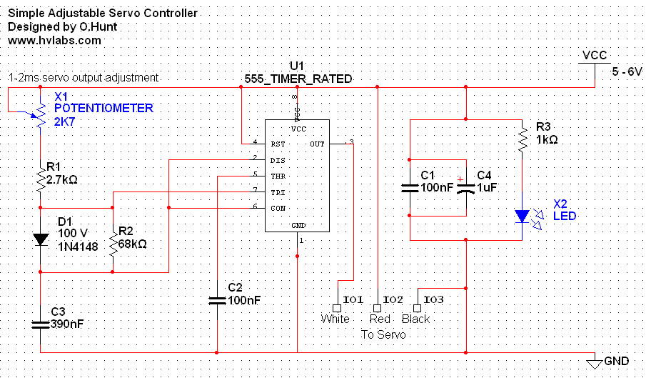
The circuit is straightforward. A 555 timer integrated circuit (IC) is utilized to generate a pulse every 20 milliseconds, with a duty cycle ranging from 5% to 10% (1-2 milliseconds). All components used are standard parts. This circuit can...
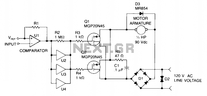
Speed control is achieved through pulse width modulation (PWM) of the gates of two MGP20N45 TMOS devices. Consequently, the motor speed is directly proportional to the pulse width of the incoming digital signal, which can be generated by a...
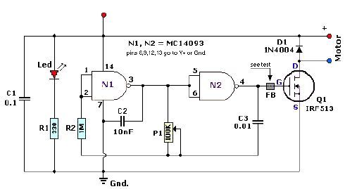
A quad 2-input NAND Schmitt trigger circuit can be designed using the MC14093 CMOS type IC, which serves as a simple pulse width modulation (PWM) controller electronic project. This PWM controller is straightforward and requires only a few external...
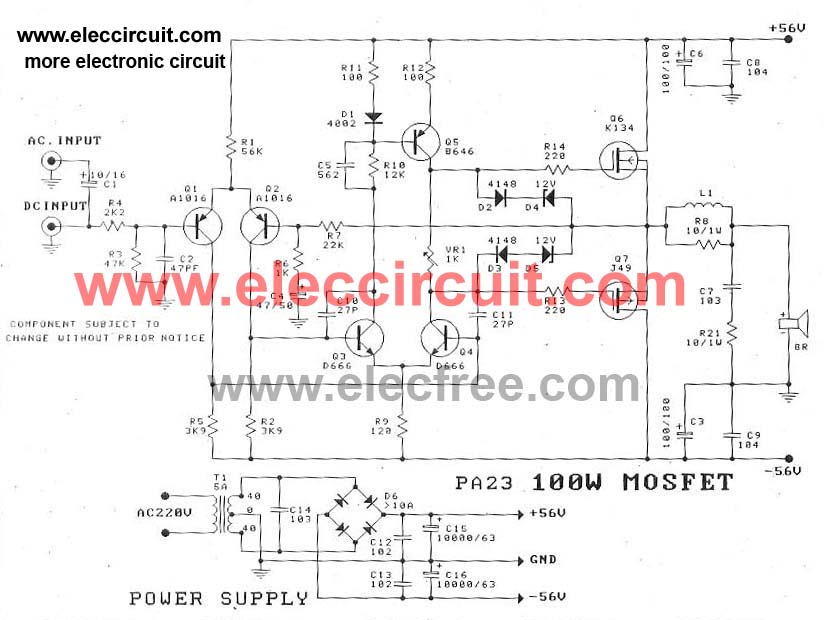
This circuit is a MOSFET power amplifier configured in an OCL (Output Capacitor-Less) topology. It delivers an output power of 100 watts and can utilize MOSFETs such as K134 and J49 or J162 and K1058. When driving an 8-ohm...