
BCD to Decimal Converter Circuit

The Binary Coded Decimal (BCD) to Decimal conversion circuit is designed to facilitate the translation of a 4-bit BCD input into its corresponding decimal output. This circuit employs standard glue logic ICs, which are versatile and can operate across different logic families as long as they share compatible voltage levels. The circuit's architecture typically includes a BCD to Decimal Decoder, which takes the 4-bit BCD input and generates a corresponding active low output for decimal values ranging from 0 to 9.
The truth table for the BCD to Decimal Decoder outlines the active low outputs for each BCD input combination. For instance, when the BCD input is 0000, the output corresponding to decimal 0 is active low, and similarly, for BCD 1001, which represents decimal 9, the output for 9 is also active low. Inputs beyond the BCD range (i.e., 1010 to 1111) result in all outputs being high, indicating that the circuit is not designed to process these values, thus maintaining output stability for inputs exceeding 9.
The circuit's design allows for seamless integration of various logic families. The operational characteristics of the circuit remain consistent across different IC series, such as the 74xx and 54xx series, with the primary difference being the temperature range specifications. This flexibility in design makes the BCD to Decimal conversion circuit adaptable for various applications in digital electronics.
In addition to the BCD to Decimal Decoder, a Decimal to BCD Encoder can be utilized to convert decimal numbers back into their BCD representation, showcasing the bidirectional nature of number representation in digital systems. The circuit's design can also be represented in multiple forms, allowing for different implementation strategies while achieving the same functional outcome of translating a 4-bit BCD code into a 9-bit binary code. This versatility is essential in digital logic design, where different configurations may be preferred based on specific application requirements.Binary Coded Decimal is a number system that only counts from 0 to 9 and then repeats. The table below shows the conversion between the different numbering systems and BCD code. BCD is also called 8421 because the binary LSB counts as a 1, the next bit adds 2, than 4 and the final MSB bit adds 8 to the final numbers. So a BCD 1001 is equal to 8 plus 1 or decimal 9 [as the table shows]. Circuit to convert Binary coded decimal to decimal. Using standard glue logic ICs; note the circuit works regardless of the particular logic standard used, as long as those families can communicate with each other over the same voltage levels. Manufacturers of Standard Glue Logic The true table for the BCD to Decimal Decoder is shown above. The output is active low and counts from 0 to 9 decimal. When all BCD inputs are low `0`, output 0 is low and so on. Note that this circuit only counts to 9, so any input higher than `9` results in all the outputs going high.
So even as the inputs continue to change the output remains unchanged in the last six entries. Functionality there is no difference between a 74xx part and a 54xx part. The difference between a 74x and 54x part is their Operating Temperature Ranges. Also refer to a Decimal to BCD Encoder [Binary coded decimal decoder]. There are a number of different ways to represent a logic function. The circuit above shows a different representation than the circuit at the top of the page. Regardless of the logic function the circuit translates a 4-bit BCD code into a 9-bit Binary code. 🔗 External reference
Related Circuits
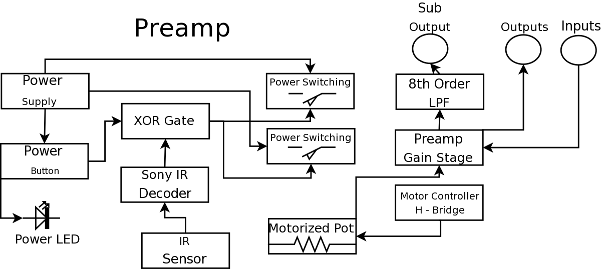
During a Digital Projects Lab, the professor suggested incorporating more circuit-level work into a project. To achieve this, a preamplifier was designed, which included an infrared (IR) remote control to replace a previously built version. The earlier preamplifier functioned...
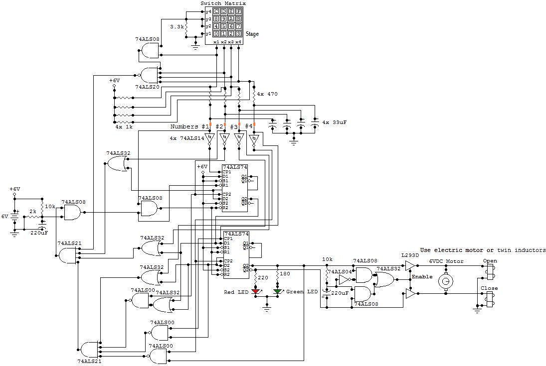
All the adapted numbers of the cipher are in the aforementioned line. To set the adjustment of the cardinal of the code, we accept to set the acceptable affiliation amid the bulge of the 7414 ascribe and the adapted...
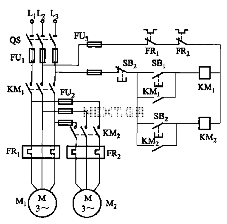
The circuit illustrated in Figure 3-83 demonstrates that the contactor KMi is activated only after it is pulled, which indicates that the motor Mi has started for the first time. Following this, the contactor KM2 is then activated, indicating...
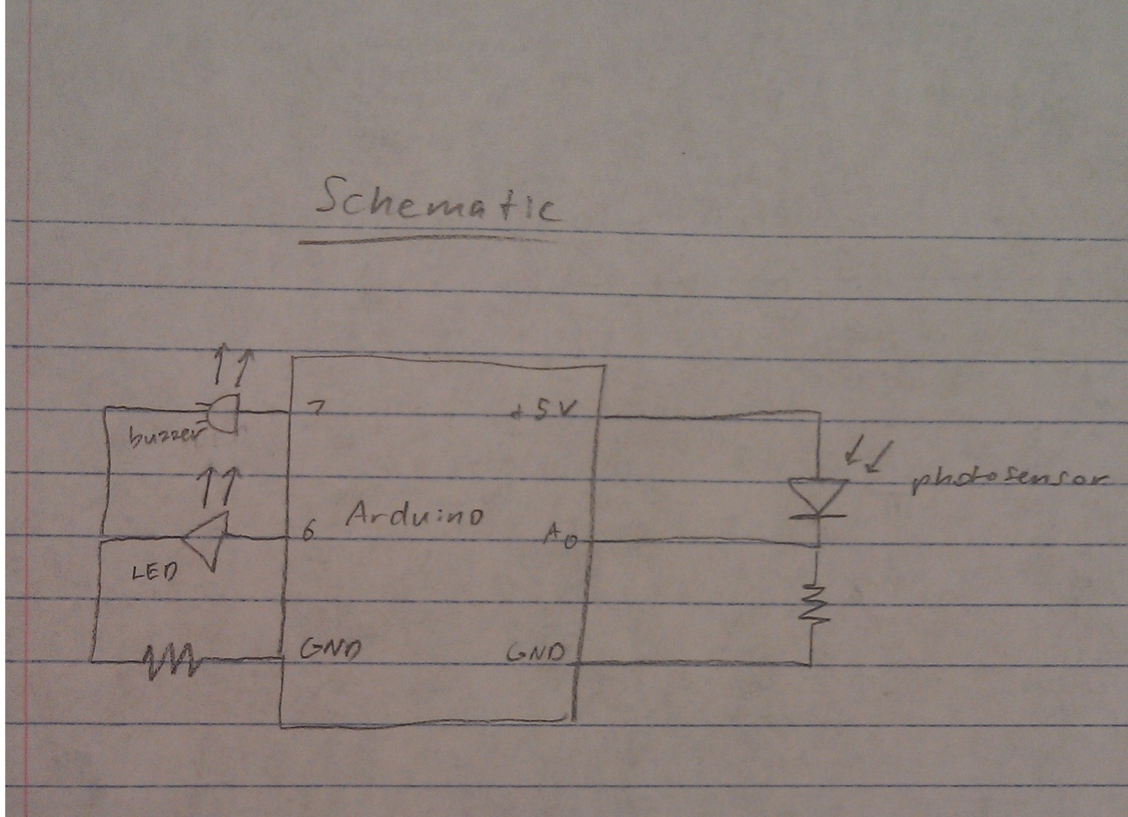
A nightlight combined with a wake-up alarm has been developed. This nightlight incorporates six LEDs that activate when a photosensor detects low ambient light levels. Additionally, a buzzer plays a cheerful tune when ambient light levels increase again. The...
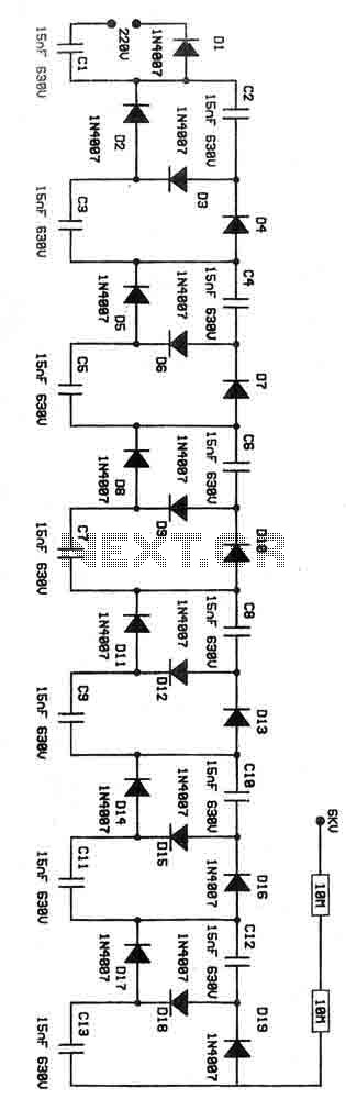
This is a voltage multiplier circuit functioning as an ionizer. It is designed to convert 220V from the mains supply into an output of approximately 6kV. Caution is advised when handling this circuit due to the potential dangers associated...
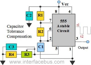
The 555 Timer is configured as an astable multivibrator. Additional components have been incorporated to enhance circuit operation. Upon powering the circuit, the 555 Timer will generate a square wave, determined by the values of Capacitor C1 and Resistors...