
Digital Bike Tachometer

The digital DIY tachometer circuit is designed to provide accurate speed measurements for bicycles by leveraging the operation of reed switches. The two reed switches are strategically located near the wheel rim, where they can detect the passing of a magnet attached to the wheel. As the bicycle moves, the magnet passes by the reed switches, causing them to open and close in response to the magnetic field.
The output from the reed switches is fed into a microcontroller, which processes the signals to calculate the rotational speed of the wheel. The microcontroller is programmed to count the number of times the reed switches are activated within a specific time frame, allowing it to compute the speed of the bicycle in real-time.
To enhance usability, the tachometer may include an LCD display that shows the current speed, average speed, and distance traveled. Power for the circuit can be supplied by a small battery, ensuring that the system remains lightweight and portable.
Additional features may include the ability to set different wheel sizes for accurate speed calculations, as well as a reset function to clear the distance traveled. The circuit should be designed with proper filtering and debouncing techniques to ensure reliable readings, minimizing errors from false triggers caused by vibrations or noise from the environment.
Overall, this DIY tachometer provides a practical solution for cyclists seeking to monitor their speed and performance on the road.This digital DIY tachometer for bikes uses two reed switches to get the speed information of the bicycle. The reed switches are installed near the rim of.. 🔗 External reference
Related Circuits
The Car Voltage Gauge is based on 3 parts. The input circuit is an Analog to Digital Converter (IC2 CA3162E). The purpose of this chip is to sample an analog voltage and convert it to a decimal value which...
This circuit, based on the 555 timer, functions as a voltmeter and an analog-to-digital converter, converting analog input voltage into digital output pulses. The 555 timer is a versatile integrated circuit commonly used for timing, oscillation, and pulse generation applications....
The digital lock utilizes four common logic integrated circuits (ICs) to manage a relay activation by inputting a four-digit code via a keypad. The initial four outputs from the CD4017 decade counter (pins 3, 2, 4, and 7) are...
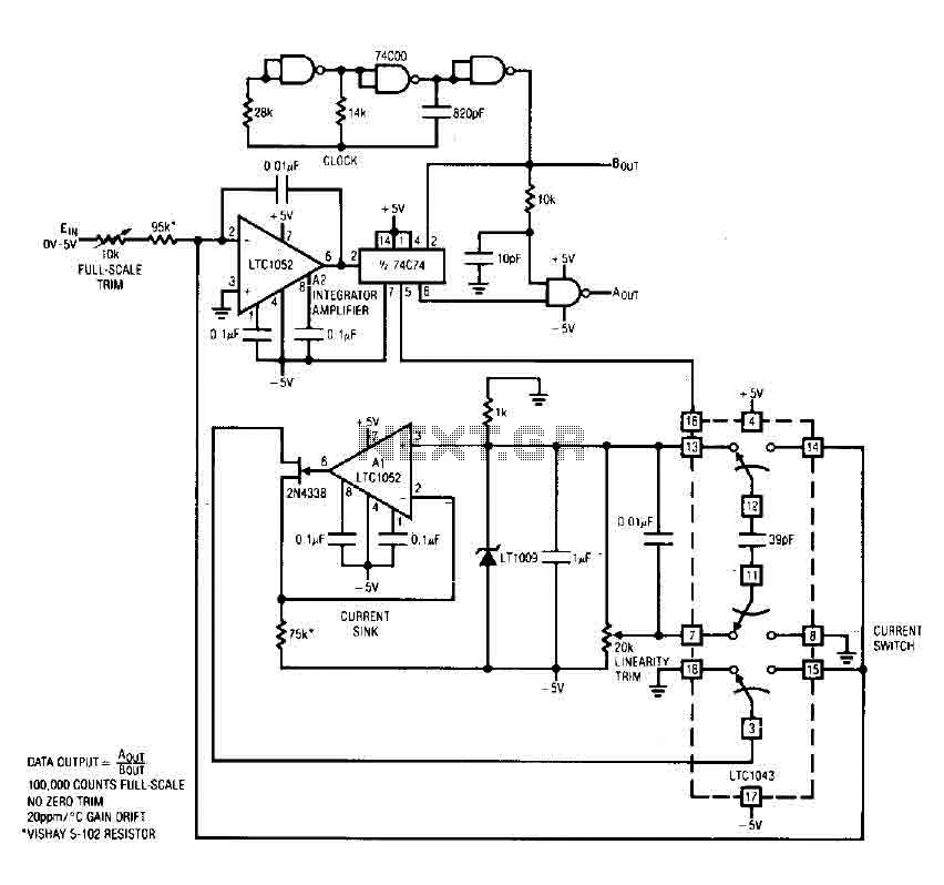
The circuit is an analog-to-digital (A/D) converter that consists of an operational amplifier (A2), a flip-flop, several logic gates, and a current sink. It employs a current balancing technique. The LTC 1052 is utilized for stabilization, ensuring that the...
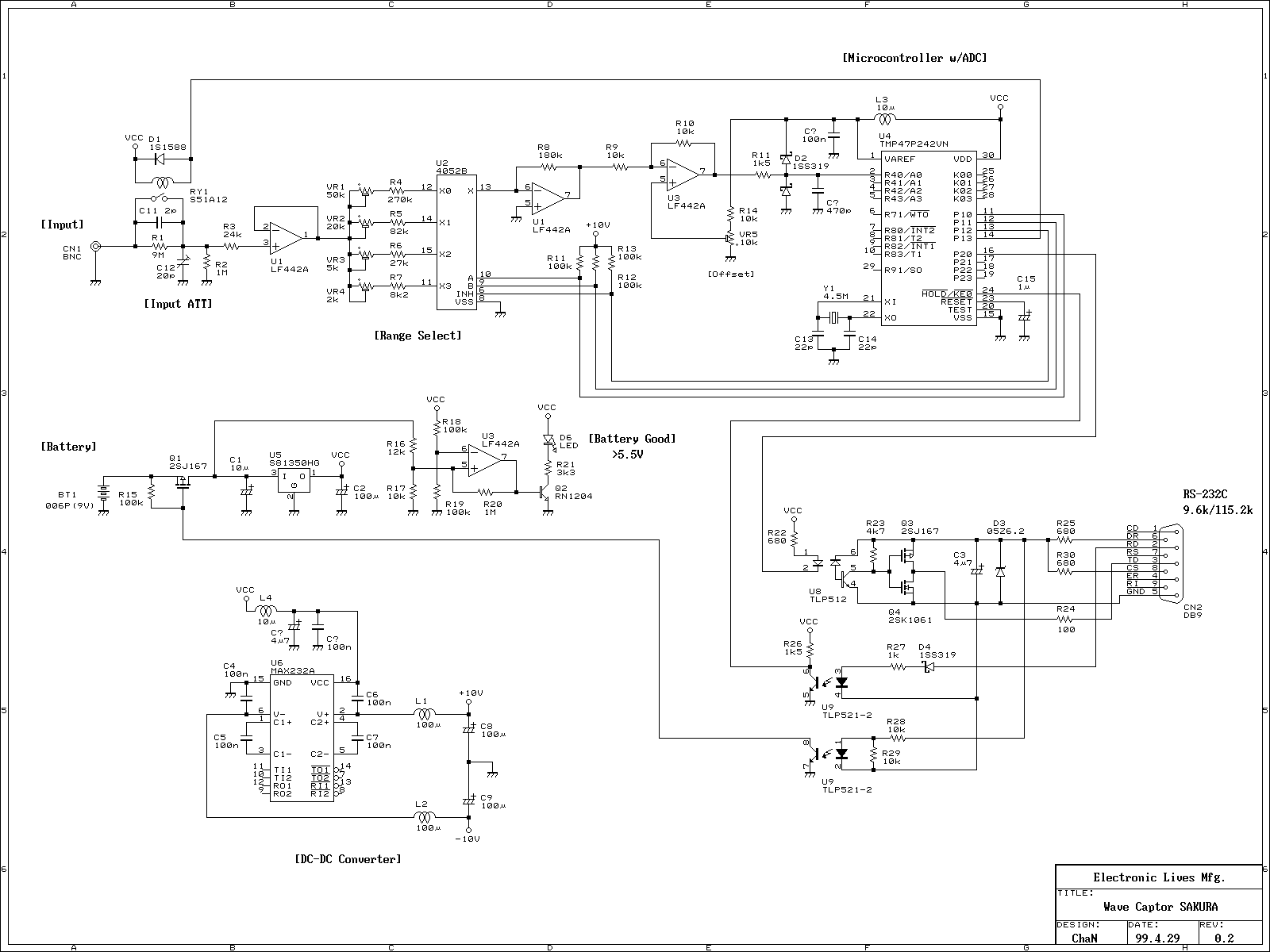
This is a portable oscilloscope adapter that can be held in a breast pocket. Its operation is only sampling and sending to the host PC. Most of the functions of the oscilloscope are processed by the host PC. Therefore,...
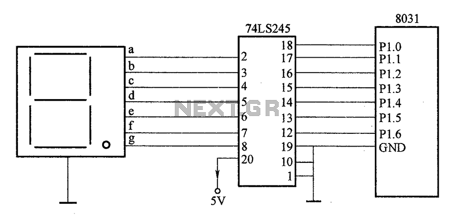
After the SCM execution, the Pl output port connects to the bidirectional input of 74LS245 driver chips. This driver operates during each phase of digital control, based on the information from the Pl port. The purpose is to convert...