
Bee Counter Theory

To summarize, the 555 timer circuit (highlighted in red) generates short pulses to activate the sensor LEDs. These pulses are directed to the LED pulser circuit (shown in green), where they are distributed to two sets of four LEDs. This configuration allows for the simultaneous pulsing of four LEDs at a time (indicated in purple), which also results in pulsing any signals from the sensors. The SR latches (depicted in orange) capture recorded signals by latching any high voltage, enabling the microcontroller to read the sensor states without needing to synchronize with the LED pulsing. After the microcontroller reads the state of each latch, it resets them to prepare for the next measurement. The demultiplexer facilitates communication between the microcontroller and over 88 sensor pins, allowing for reading and resetting of each sensor with a minimal number of microcontroller pins—potentially as few as fifteen pins for forty-four sensors.
The Bee Counter test board schematic is designed with efficiency and simplicity in mind, enabling effective testing and debugging of the overall system. The 555 timer circuit serves as the timing mechanism, providing consistent pulse outputs that are critical for the operation of the sensor LEDs. The LED pulser circuit is responsible for controlling the timing and sequencing of the LED activation, ensuring that the sensors are adequately illuminated during their operational cycles.
The SR latch configuration is integral to the design, as it allows the microcontroller to capture and store sensor readings independently of the LED pulsing. This asynchronous operation is crucial for accurate data collection, as it prevents the interference of LED activation with sensor signal readings. The microcontroller's ability to reset the latches after reading ensures that the system is ready for new data, thereby maintaining a continuous flow of information.
The implementation of a demultiplexer within the circuit architecture is a strategic choice that optimizes the use of microcontroller pins. By allowing multiple sensor inputs to be managed with fewer pins, the design enhances scalability and flexibility, making it easier to expand the system in future iterations or adaptations. This careful consideration of component selection and circuit layout reflects a well-thought-out approach to designing a functional and effective Bee Counter system.Here's the schematic for my Bee Counter test board with the functional units labeled to make them easier to discuss. This test board has the same circuitry as the larger board, but with only 4 gates instead of 44 to save a TON of time and money debugging it.
I should warn you that I haven't seen it work yet, so there's nearly a 100% chance that it won't work as drawn, but I'm pretty confident the design is solid even if my wiring or resistor values are off a bit, or if I somehow specified chips that won't work together. To summarize, the 555 timer circuit (in red) puts out short pulses that will be used to pulse the sensor LEDs. The pulses are sent to the LED pulser circuit (green). There they are routed to each set of 4 LEDs (only 2 sets in this test board). This pulses the LEDs 4 at a time (purple), but this means that any signal from the sensors is pulsed as well.
The SR Latches (orange) save a recorded signal (latching any high voltage) so the microcontroller can read the sensors without synchronizing the reading with the LED pulsing. After reading the state of each latch, the microcontroller will reset each latch so they're ready to record another measurement.
The demultiplexer simply allows the microcontroller to read and write to the 88+ sensor pins (read and reset for each sensor) with a minimum number of microcontroller pins (as few as 15 pins for 44 sensors) 🔗 External reference
Related Circuits
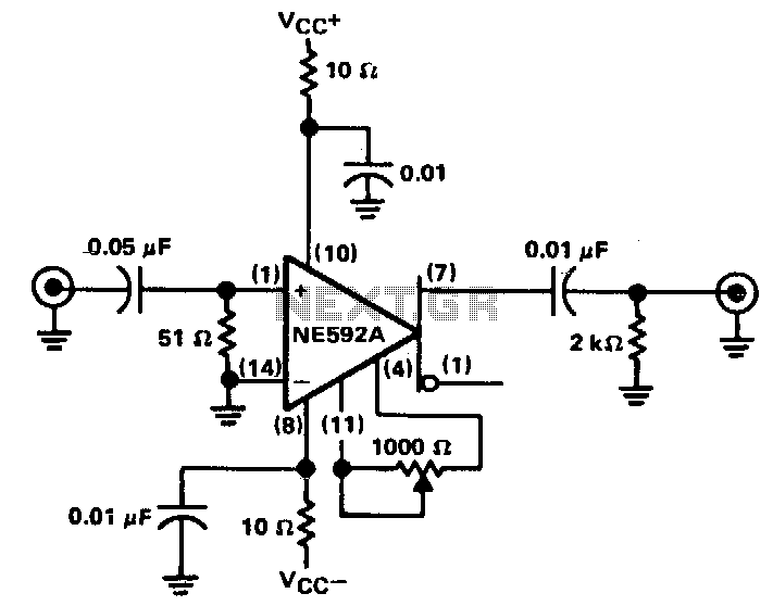
The circuit provides a voltage gain of 20 ±0.1 dB within a frequency range of 500 kHz to 50 MHz. The low-frequency response of the amplifier can be enhanced by increasing the value of the 0.05 µF capacitor connected...
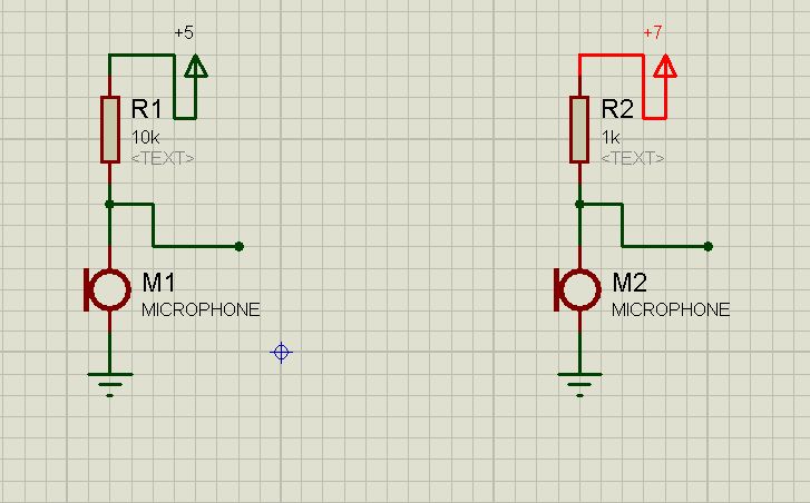
How can one theoretically determine the output of a capacitor microphone, or estimate it without testing? For instance, in the following circuits, what is the output of each? The output of a capacitor microphone, also known as a condenser microphone,...
This project involves an automatic room light controller with a visitor counter utilizing a microcontroller. It is a dependable circuit designed to manage room lighting while accurately counting the number of individuals present. When a person enters the room,...
This circuit is designed for alerting purposes after a specified duration has elapsed. It is suitable for table games that require a fixed time limit to answer a question or to move a piece, serving as a modern substitute...
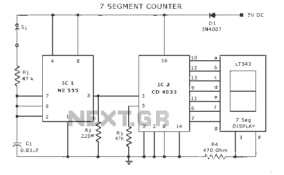
A display counter circuit is illustrated through a diagram featuring a seven-segment display controlled by the counter IC CD4033. This counter circuit is designed to visually represent incremental counts, enhancing its appeal for integration into various applications. An astable...
The preamplifier is based on the LM733 or NE592, featuring a bandwidth of 100 MHz. The FET inputs offer an input impedance of approximately 1 MΩ. Signal conditioning is achieved through the use of Q4, Q5, and IC2. The...