
find the output of capacitor microphone in theory or augur
The output of a capacitor microphone, also known as a condenser microphone, is influenced by several factors including the circuit configuration, power supply, and the characteristics of the microphone itself. The basic operation of a capacitor microphone involves a diaphragm that vibrates in response to sound waves, creating variations in capacitance that are converted into an electrical signal.
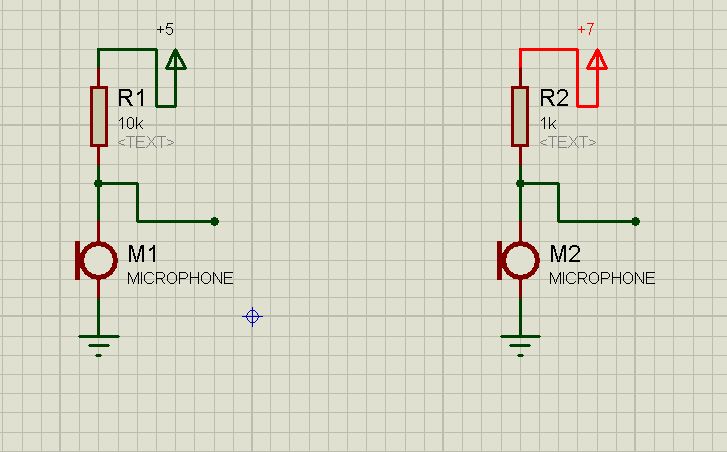
In a typical circuit, the capacitor microphone is connected in parallel with a biasing resistor and often coupled with an amplifier to boost the signal for further processing. The output voltage can be calculated using the formula V_out = (V_bias * C_microphone) / (C_microphone + C_load), where V_bias is the bias voltage supplied to the microphone, C_microphone is the capacitance of the microphone, and C_load is the load capacitance in the circuit.
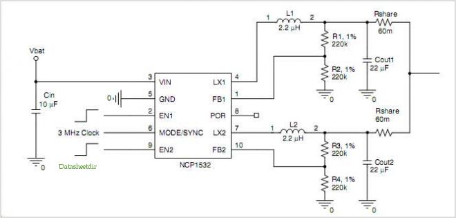
In practical applications, the output will also depend on the frequency response of the microphone and the impedance of the connected load. Additionally, various circuit configurations such as using an operational amplifier can significantly enhance the output signal and improve the signal-to-noise ratio. Understanding these parameters is essential for accurately predicting the output of a capacitor microphone in different circuit setups.Hello how can find the output of capacitor microphone in theory or augur it without test in? for example in these circuits what is the output of each.. 🔗 External reference
Related Circuits
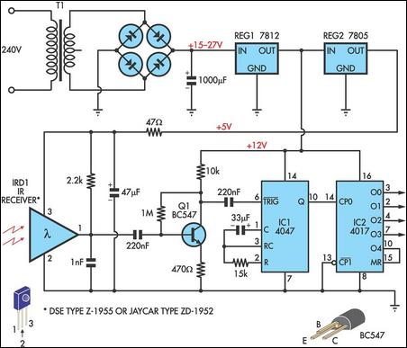
This circuit allows any infrared (IR) remote control to manage the outputs of a 4017 decade counter. It utilizes a 3-terminal IR receiver (IRD1) to capture infrared signals from the transmitter. The output from IRD1 is connected to an...
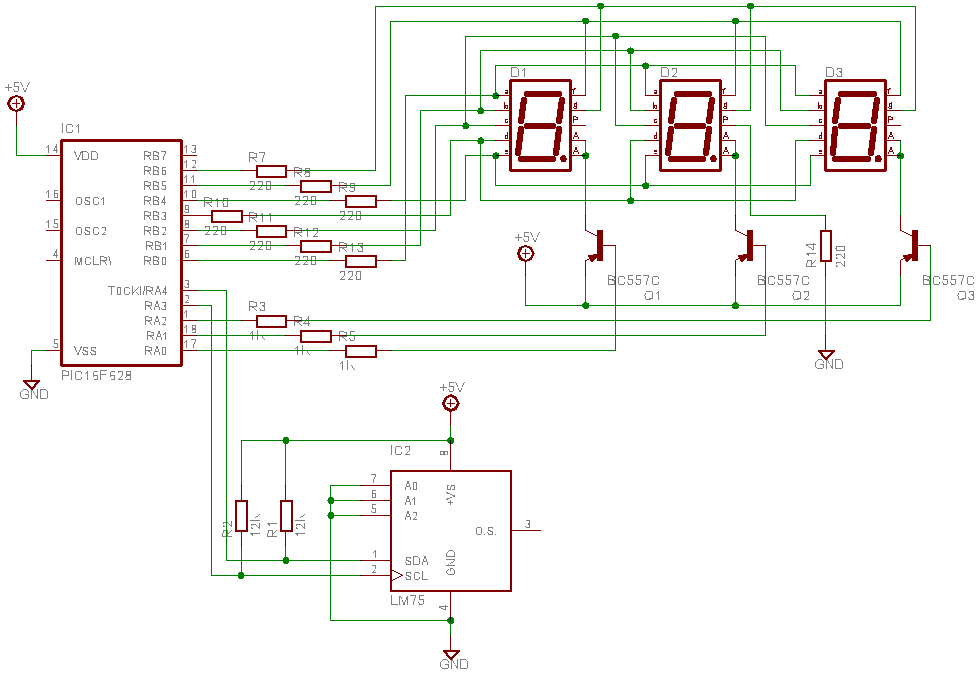
This is a test project assembled quickly on a solderless breadboard. It utilizes an LM75 temperature sensor to read the current temperature through the I2C communication protocol and displays the result. The project employs the LM75, a digital temperature sensor...
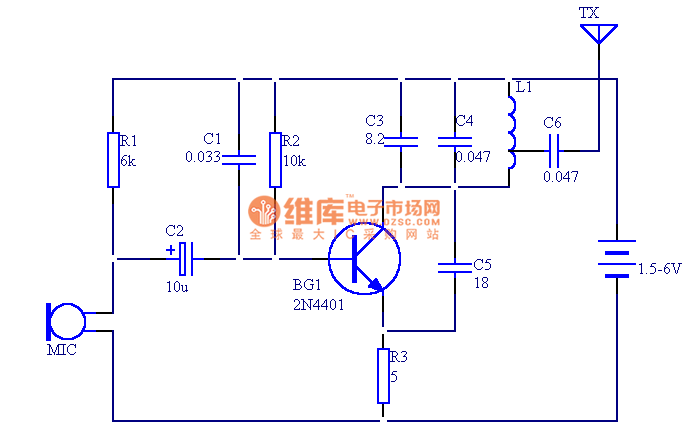
The circuit presented in this document utilizes 12 components to create a compact wireless FM microphone that operates with a stable frequency. The effective transmission range is approximately 30 meters, extending to over 100 meters when powered by a...
The Hopping Decoder is utilized in conjunction with the Hopping Encoder device to decode address data, key data, and rolling data. It employs the DES24 encryption algorithm for decoding. Each time the Hopping Encoder key is activated, the rolling...
The design consists of differential compound pairs of transistors with a common mode (floating) gain control connecting the emitters of the pair. The compound pairs of 2N4403 and BC549s are far more linear than any single transistor. The circuit...
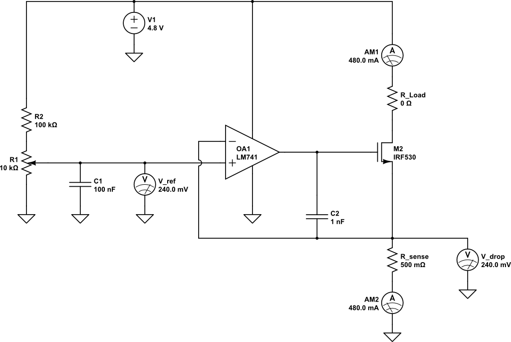
A current limiting circuit is designed to select a maximum current through a load, set to a maximum of 480 mA. As the load resistance increases, the series equivalent resistance (SER) of the limiting circuit decreases. When charging a...