
10 to 15 MHz AM Transmitter Circuit

This AM transmitter circuit operates within the frequency range of 10 to 15 MHz, making it suitable for various amateur radio applications. The use of a ½J gang condenser (VC1) allows for precise tuning of the carrier frequency, while inductor L1 works in conjunction with VC1 to establish the desired frequency. The additional frequency trimming capability provided by VC2 ensures that the output remains stable and accurate.
The signal amplification is achieved through a series of transistors, starting with T4, which amplifies the carrier signal. The RF amplifier stage, based on transistor T1 (BD677), is crucial for boosting the RF signal to a level suitable for transmission. Transformer X1 plays a vital role in coupling the amplified carrier signal to the RF amplifier while providing isolation between stages.
The audio input, captured by the condenser microphone, is first preamplified by transistor T3 (BC548). This preamplification is essential for ensuring that the audio signal is strong enough for further processing. The amplified audio signal is then fed into transistor T2 (BD139), which modulates the RF signal produced by T1. The modulation process involves varying the current through T1 based on the amplitude of the audio signal, effectively encoding the audio onto the RF carrier wave.
RFC1 serves an important function in the circuit by blocking any unwanted RF signals from T2 from reaching the power supply, thereby preventing interference and ensuring stable operation of the transmitter. This design demonstrates an efficient and cost-effective approach to building an AM transmitter suitable for hobbyists and educational purposes in radio communications.This low-cost AM transmitter is tunable from 10 to 15 MHz with the help of ½J gang condenser VC1, which determines the carrier frequency of the amplitude modulation transmitter in conjunction with inductor L1. The frequency trimming can be done with VC2. The carrier is amplified by transistor T4 and coupled to RF amplifier transistor T1 BD677 thr ough transformer X1. The AM radio transmitter does not use any modulator transformer. The audio output from condenser MIC is preamplified by transistor T3 (BC548). The audio output from T3 is further amplified by transistor T2 (BD139), which modulates the RF amplifier built around transistor T1 by varying the current through it in accordance with the audio signal`s amplitude. RFC1 is used to block the carrier RF signal from transistor T2 and the power supply. 🔗 External reference
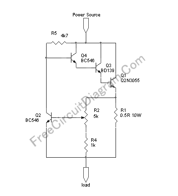
Related Circuits
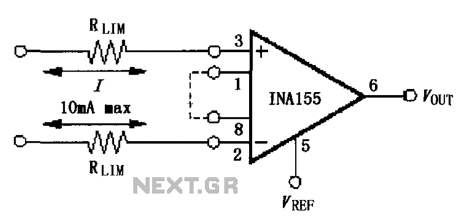
The input current protection circuit is illustrated in FIG, utilizing INA155/156. The INA155 features internal electrostatic discharge (ESD) protection diodes that become active when the input voltage exceeds the supply voltage by 500mV. In this scenario, the protection diodes...
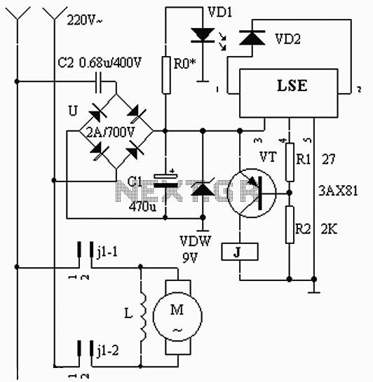
The circuit operates based on the interaction between an infrared light-emitting diode (VD1) and an infrared receiver diode (VD2). When VD1 emits infrared radiation, it is detected by VD2, which causes a decrease in its internal resistance. This change...
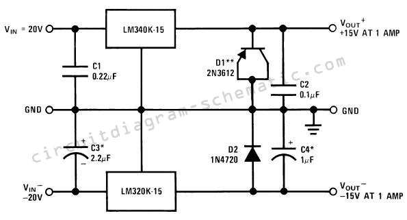
The circuit consists of a series of dual power supplies, providing a symmetrical ±15V supply for linear circuits. The same principle is applicable to non-symmetrical supplies, such as 5.0V and -12V regulators, which are used in applications like registers....

Power Amplifier Speaker Protection Circuit Schematic. When a power amplifier is switched on, a loud thump sound is often heard due to a sudden heavy discharge. The power amplifier speaker protection circuit is designed to prevent loud thump sounds during...
A novel application of solar cells simplifies the process of positioning a car in a garage, offering an improvement over traditional methods such as using old tires, mirrors, or chalk marks. The six solar cells depicted in Figure 1...
This circuit provides automatic current limiting up to 8.4 A. Unlike current limiters that use only a resistor, this current limiting circuit does not drop the voltage significantly or keeps the voltage drop to a minimum until a specific...