
Rs-232C Line-Driven Cmos Circuits

The circuit is designed to efficiently convert the voltage levels from RS-232C communication lines into a usable power source for CMOS devices. The MAX680, a voltage regulator, plays a crucial role in this process by stabilizing the output voltage. The use of Schottky or silicon diodes is critical, as they provide low forward voltage drop, enhancing the efficiency of the rectification process.
The energy harvesting mechanism relies on the rectification of the RS-232C signal, which, when combined with the capacitive storage, allows for the generation of a stable output voltage. The capacitors connected to the V+ and V- pins are essential for smoothing out the rectified voltage and ensuring that the MAX680 operates within its specified parameters.
The reverse charge pumping action facilitated by capacitors C1 and C2 is a clever design choice, enabling the circuit to boost the voltage to the desired level. The relationship between the number of diodes used and the output current capacity is significant; as more diodes are added, the effective source resistance decreases, thereby allowing for greater current delivery without compromising the voltage stability.
In applications where higher current is needed, the parallel configuration of two MAX680 devices provides flexibility and scalability. Each device can independently manage its input capacitors, ensuring that variations in load do not adversely affect performance. Care must be taken to avoid exceeding the current ratings of the RS-232C lines, which could lead to signal integrity issues or potential damage to the communication interface.
This circuit is particularly useful in environments where CMOS devices require stable power supplies derived from existing communication lines, thus enhancing the versatility and functionality of RS-232C interfaces in electronic systems. The circuit illustrates a way to power CMOS ICs from RS-232C lines. The MAX680 is normally used to genera te a voltage equal to ±2 Vcc· This circuit does exactly the opposite. It takes in±10.5to±12V on the DTR and TD lines and puts out a 5.25- to 6-V signal. A pair of Schottky or silicon diodes rectifies each RS-232C line. The resultant energy is stored by the capacitors attached to the IC"s V + and V - pins. CI or both CI and C2 then reverse-charge pump the energy stored at the V + and V- pins to C3. The input source current of the MAX680 is approximately equal to the voltage drop of any one of the diodes that is divided by the series resistance of 160 . When you drive this circuit from a 1488 driver with a ± 12-V supply, it can deliver 5 V at 3 mA. To increase the output current, you can use as many as three sets of diodes on each RS-242 line to provide 5 V at 8 mA.
The more diodes you use, the lower the source resistance: Rs equals the inversion of the sum of the diodes" conductances. If your circuit requires even more output current, you can place two MAX680s in parallel, tie their V+ and V- capacitors together, and use separate CI and C2 capacitors for each ship.
If you do connect the devices in parallel, make sure not to exceed the power capability of the RS-232C lines.
Related Circuits
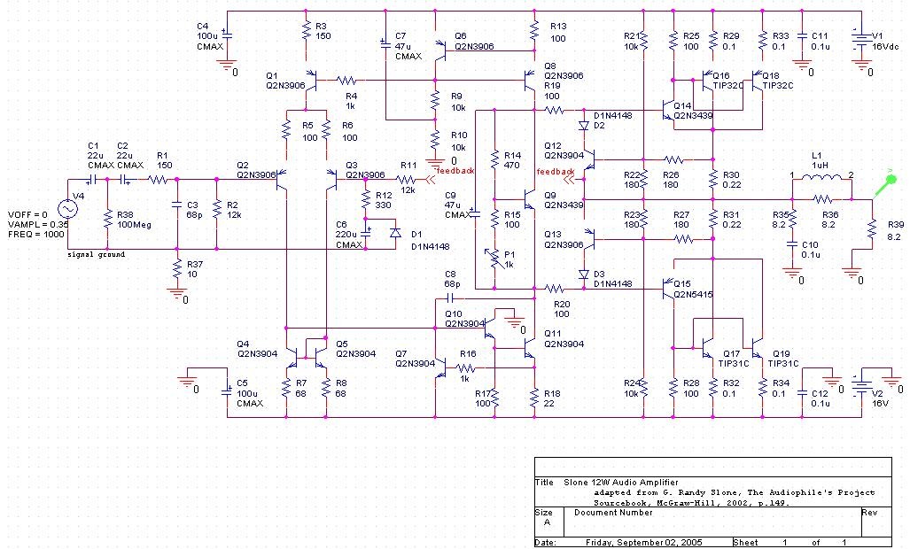
The project involves developing a 12W power amplifier circuit into a fully assembled hard-wired unit. This will require a design cycle and development sequence that includes analysis, simulation, printed circuit board (PCB) layout, board population, hard soldering, and testing....
This weblog focuses on electronic circuit schematics, PCB design, DIY kits, and diagrams for various electronic projects. It features a mixer that demonstrates how to create microphone pre-amplifiers suitable for both low and high impedance microphones. The design utilizes...
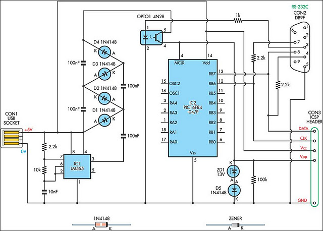
A small biped walker constructed from 2mm plywood, powered by two RC servos. It utilizes the widely available and programmable flash microcontroller PIC16F84. This simple circuit is designed to program the PIC16F84 and similar flash memory components. The project...
An active amplified transformer isolated signal splitter that enables a hum-free connection of one guitar to multiple amplifiers, while also providing a direct output. This includes a discussion on using audio transformers for equipment interconnections and mentions line-level transformers...
This discussion covers three different Xenon flashing circuits from disposable cameras. From these circuits, unique techniques not found in any theoretical literature will be presented. The first circuit consists of six building blocks. An old disposable flash camera and...
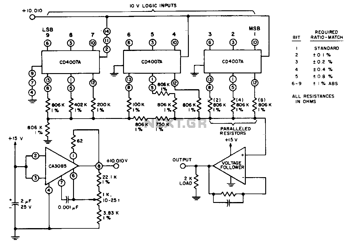
Three CD4007 A integrated circuit packages perform the switching function using a 10-V logic level. A single 15-V supply provides a positive bus for the follower amplifier and powers the CA3085 voltage regulator. The scale adjustment function is facilitated...