
Before power is in the release state holding brake circuit

The circuit described operates through a sequence of interconnected components designed to manage the motor's operation effectively. The stop button SBz serves as the primary control input, initiating the shutdown sequence when pressed. Upon activation, contact KMi opens, severing the power supply to the motor, which halts its operation. The simultaneous engagement of KMz activates the electromagnetic brake YB, ensuring that the motor does not inadvertently restart or move during the shutdown process.
The time delay relay KT introduces a critical timing function into the circuit. It is configured to maintain its normally closed contacts in the initial state, allowing current to flow in the circuit. Once the stop button is pressed, KT begins its timing cycle. After the designated delay period elapses, KT closes its contacts, which causes KM2 to release. This action restores the circuit to its pre-operation state, allowing for a safe and controlled restart of the motor when ready.
This circuit design is particularly useful in applications where motor control and safety are paramount, such as in industrial machinery or automated systems. The integration of a time delay relay adds an essential layer of safety, preventing immediate re-engagement of the motor and allowing for any necessary maintenance or checks to be performed before the system is reactivated. Circuit shown in Figure 3-123. When you press the stop button SBz, contact KMi release, cut off the power to the motor, at the same time, KMz pull, turn the electromagnetic bra ke YB power supply, the motor hold Brake. After a period of time delay, time delay relay KT close the normally closed contacts disconnect, KM2 release, the circuit before starting the recovery state.
Related Circuits
A 100W RF power amplifier circuit is constructed using two BLY94 transistors. For additional RF amplifier options, refer to the list below. Components include active components. The 100W RF power amplifier circuit utilizing BLY94 transistors is designed to amplify radio...
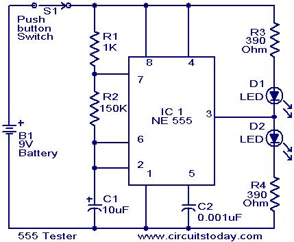
The NE555 timer is configured as an astable multivibrator. When the push button switch S1 is pressed, the LEDs D1 and D2 will flash alternately. When the output is high, D2 will illuminate, and when the output is low,...
The main feature of this power supply is its selection of outputs at standard fixed voltages commonly used in electronics. Since the outputs are fixed, there is no need to worry about voltage correctness; simply plug in the wire...
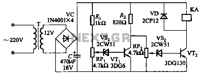
The circuit employs a transistor control mechanism. When the grid voltage is within the normal range, relay KA is activated, supplying power to the load. If the grid voltage falls below the minimum allowable threshold (adjustable via potentiometer RPz)...
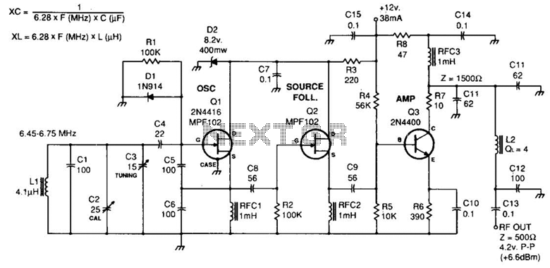
Fixed-value capacitors are disc ceramics. C1, C4, C5, C6, and C8 are NPO ceramic or polystyrene. C2 is a 25-pF ceramic trimmer and C3 is a 15-pF miniature air variable capacitor. The resistors are ¼ watt carbon film or...
The function of the sound level display circuit is to enhance the appearance of an amplifier circuit or a radio player. It provides an impressive visual representation of audio levels. The sound level display circuit serves as a visual indicator...