
Mains undervoltage overvoltage protection circuit

The described circuit functions as a protective relay system designed to monitor and control power supply to a load based on grid voltage levels. The core component of this circuit is a transistor, which serves as a switch that controls the operation of relay KA.
In normal operation, when the grid voltage is stable and within the predefined limits, the transistor is biased appropriately, allowing current to flow through its collector-emitter path. This action energizes relay KA, which closes its contacts and connects the load to the power supply.
The circuit includes two adjustable resistors: RPz and RPi. RPz is used to set the minimum allowable voltage threshold, while RPi establishes the maximum allowable voltage threshold. These thresholds can be fine-tuned according to the specific requirements of the application.
When the grid voltage drops below the set minimum (as determined by RPz), or rises above the set maximum (as determined by RPi), the transistor's biasing conditions change, causing it to turn off. This action deactivates relay KA, opening its contacts and cutting off power to the load to prevent damage from overvoltage or undervoltage conditions.
The implementation of this circuit enhances the reliability and safety of electrical systems by ensuring that loads are only powered when grid voltage is within acceptable limits. Additionally, the use of a potentiometer allows for easy adjustments to the threshold values, providing flexibility in various applications.It uses a transistor control circuit. When the grid voltage is normal, relay KA pull, turn the power load. When the grid voltage is below the minimum allowable value (can be set by the potentiometer RPz), or higher than the maximum allowable value (by RPi setting), KA is released, the load can be cut off the power supply.
Related Circuits
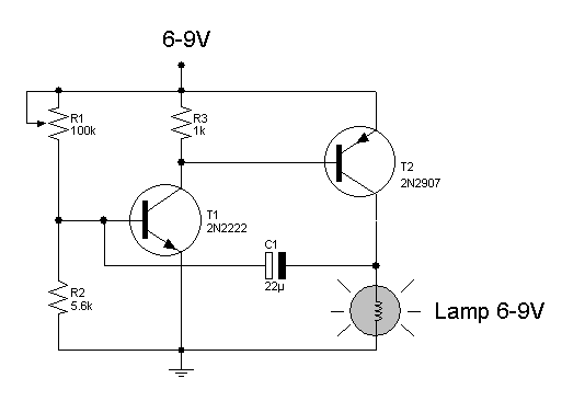
Light flashing circuit. This circuit is designed to create a small lamp that flashes with a signal at a rate of one flash per second, controlled by adjusting the lamp voltage through resistor R1. The rate is adjustable to...
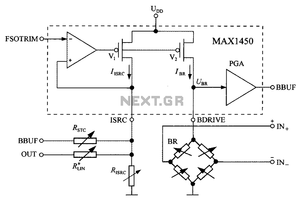
The circuit diagram for the bridge integrated pressure signal conditioner MAX1450 is composed of various components. The MAX1450 is a high-performance integrated circuit designed for signal conditioning in pressure sensing applications. It is particularly suited for use with resistive bridge...

The device is a DC switch that remains normally on due to the forward biasing of Q1 through resistor R3. Q1 clamps Q2 into a forward state by biasing its complementary transistor well into saturation via resistor R4. The...
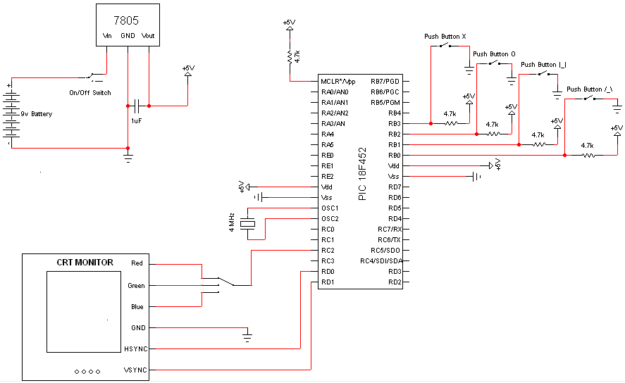
Very few electronic components are required for this project, as the PIC Microcontroller serves as the primary processing unit. The essential components include buttons, switches, and a power circuit, which are straightforward forms of input/output, facilitating an easier understanding...
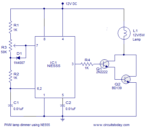
A simple PWM lamp dimmer using the NE555 timer IC. The 555 timer IC is configured as a variable duty cycle astable multivibrator to control the brightness of the lamp. The described circuit utilizes the NE555 timer IC, a versatile...
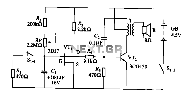
The darkroom circuit is designed for one-time exposure and emits an audible signal when the developing time is reached. This circuit can be utilized for photofinishing large timers and other applications. It comprises components such as FET VTi, resistors,...