
Beginner Circuit question

Understanding circuit diagrams is essential for anyone involved in electronics, as they serve as a visual representation of electrical circuits. These diagrams utilize standardized symbols to represent various components, such as resistors, capacitors, diodes, and integrated circuits, along with lines to indicate the connections or paths for electrical current.
To read a circuit diagram effectively, one should first familiarize themselves with the common symbols used in the diagrams. For example, a straight line typically represents a wire, while a zigzag line may denote a resistor. It is also important to understand the flow of current, which is usually indicated by arrows.
The arrangement of wires in a circuit diagram is not necessarily indicative of their physical layout on a circuit board. Instead, the diagram focuses on the functional relationships between components. Therefore, it is crucial to follow the connections as they are depicted, ensuring that the correct components are linked as intended.
To further enhance comprehension, it is advisable to study simple circuit examples, gradually progressing to more complex diagrams. Hands-on practice with building circuits based on these diagrams can also be beneficial. Utilizing simulation software can provide an interactive experience to visualize how the circuit operates without the need for physical components.
In conclusion, developing proficiency in reading circuit diagrams requires practice and familiarity with electronic symbols and conventions. Engaging with practical examples and simulations can significantly aid in mastering this essential skill in electronics.Hi I am new to electronics and have some questions about reading circuit diagrams. When I look at circuit diagrams I don`t know which order the wires, .. 🔗 External reference
Related Circuits
The input signal is applied to a gate G and then to a counter for a precise period of time. After this period, the input signal is stopped for a while, and then the cycle is repeated. During the...

This document illustrates the configuration of the high-precision, high-impedance OPA2111 amplifier. The total voltage circuit is designed for a magnification of Av = 10 (1 + 2R2 / R1), achieving a total gain of 1000 times. A gain stage...
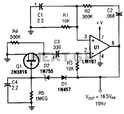
This Wien-bridge sine-wave oscillator utilizes a 2N3819 as an amplitude stabilizer. The 2N3819 functions as a variable-resistance element within the Wien bridge. The Wien-bridge oscillator is a type of electronic oscillator that generates sine waves. It employs a bridge circuit...
Measuring the temperature of coffee is important because the taste of coffee relies on two main factors: the strength of the coffee and its temperature. Measuring the temperature of coffee can be accomplished using a simple electronic circuit designed to...

The temperature alarm circuit shown in the figure consists of an inverting amplifier (IC1), a comparison amplifier (IC2), a low-frequency multivibrator (IC3), a controllable oscillation frequency multivibrator (IC4), a bridge measurement network, a speaker (Y), and a power supply...

Another application of the frequency-to-voltage converter (FVC) is the tone/frequency decoder. This circuit is designed to identify the frequency band of an oscillating signal. It is utilized in various applications, such as determining the frequency band in signals and...