
Frequency/Tone Decoder Circuit Using TC9400 FVC

The frequency-to-voltage converter (FVC) circuit serves as a critical component in applications requiring precise frequency detection and decoding. The TC9400 F/V converter is a specialized integrated circuit that efficiently converts input frequency signals into corresponding output voltage levels. This conversion is essential because most digital systems require analog voltage levels for processing and interpretation.
In this configuration, the TC9400 is connected to the input signal, which may originate from various sources, such as oscillators or RF signals. The output from the TC9400 is a voltage that is directly proportional to the input frequency, enabling straightforward interpretation of frequency changes as voltage variations.
The quad comparator integrated into the circuit plays a vital role in monitoring the output voltage levels. It is configured to compare the output voltage from the TC9400 against predefined threshold levels. When the output voltage exceeds these thresholds, the comparators generate logical high signals at their outputs, indicating that the frequency has crossed specified limits. This functionality is crucial for applications like remote control systems, where different frequencies correspond to different commands, allowing the system to respond appropriately based on the detected frequency.
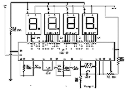
The circuit's design may include additional components such as resistors and capacitors to filter noise and stabilize the output voltage, ensuring reliable operation in various environments. The logical outputs can be interfaced with microcontrollers or other digital systems to execute commands based on the detected frequency. Overall, this frequency-to-voltage converter circuit exemplifies a versatile solution for frequency detection and decoding in modern electronic applications.Another application of FVC (frequency-to-voltage converter) is tone/frequency decoder. This circuit is used to determine the frequency band of an oscillation signal. This circuit is used in many application like determines the frequency band in the signal and remote control where the frequency band corresponds to a different command. This circuit uses TC9400 F/V converter to convert the frequency to voltage because the frequency must be converted to proportional analog voltage before can be detected. This is the figure of the circuit; Beside TC9400 F/V converter, this circuit also uses the quad comparators.
It used to detect when the frequency limits is exceeded by the voltage (frequency). The frequency is indicated by the logical 1 ³ at any of the five output. [Circuit diagram source: Microchip Application Note] 🔗 External reference
Related Circuits
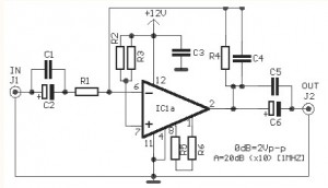
The video amplifier circuit utilizes the LM359 integrated circuit, which is a dual, high-speed, programmable current mode (Norton) amplifier. This circuit is suitable for general-purpose video amplification applications. The LM359 is designed to operate as a high-speed amplifier, making it...
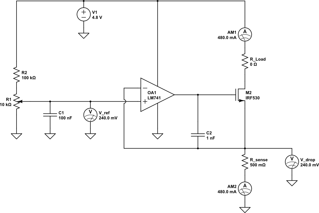
A current limiting circuit is designed to select a maximum current through a load, set to a maximum of 480 mA. As the load resistance increases, the series equivalent resistance (SER) of the limiting circuit decreases. When charging a...
This document provides a guide on understanding a simple computer system and its operation. It will examine the BASIC programming language and its statements, enabling communication with external circuitry. The document will also explore how to interface electronic circuits...
A battery-status indicator circuit is useful for monitoring portable test equipment and similar devices. LED D1 flashes to attract the user's attention, signaling that the circuit is operational, preventing it from being left on unintentionally. The circuit produces approximately...

The difference between instantaneous frequency and central frequency of the carrier is directly proportional to the instantaneous value of the amplitude of the message signal. A 555 Timer configured in Astable Mode can be utilized for generating Frequency Modulated...
The circuit presented is a highly effective and precise digital voltmeter with an LED display utilizing the ICL7107 from Intersil. The ICL7107 is a high-performance, low-power, 3.5-digit analog-to-digital converter (ADC). This integrated circuit (IC) incorporates internal components such as...