
Bench top power supply

The circuit begins with a tapped transformer that provides multiple voltage outputs based on the selected tap via switch S2a. The diode bridge rectifies the AC voltage produced by the transformer into a pulsating DC voltage. The two 2500 µF filter capacitors (C1 and C2) smooth out the rectified output, yielding a stable DC voltage of either 37 volts or 47 volts, depending on the transformer tap selected.
The unregulated DC voltage is then directed to a pre-regulator stage composed of a transistor (Q1) and a Zener diode (D5). This stage is crucial for protecting the voltage regulator IC (IC1, the 723) from voltage levels exceeding its maximum rating of 40 volts. The Zener diode clamps the voltage to a safe level, ensuring that IC1 operates within its specified limits.
An LED (LED1) connected with a 2.2 kΩ current-limiting resistor (R1) serves as a power indicator, illuminating when the circuit is powered. The LED's brightness may vary slightly with different transformer taps, but this variation does not significantly impact the overall functionality of the circuit.
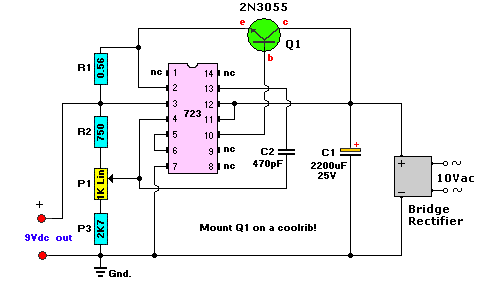
The 723 voltage regulator IC is designed to maintain a constant output voltage by adjusting the pass transistor (Q2) in response to load changes. Q2, configured as a voltage follower, provides current amplification, allowing the circuit to deliver sufficient current to the load. With a maximum collector current rating of 15 amps and a maximum VCE of 70 volts, Q2 is well-suited for this application, ensuring reliable performance under varying load conditions. This design effectively combines voltage regulation and power handling capabilities, making it suitable for various electronic applications.A tapped transformer drives a diode bridge (D1-D4) and two 2500 µ¥ filter capacitors (Cl and C2), that provide a no-load voltage of 37 or 47 volts, depending upon the position of switch S2a. The unregulated dc is then fed to a pre-regulator stage composed of Ql and D5. Those components protect IC1 (the 723) from an over-voltage condition; the 723 can't handle more than 40 volts.
The LED (LED1) and its 2.2 k current-limiting resistor (Rl) provide on/off indication. The current through the LED varies slightly according to the transformer tap selected, but that's of no real consequence. The series-pass transistor in IC1 drives voltage-follower Q2, providing current amplification. The transistor can handle lots of power. It has a maximum collector current of 15 amps and a maximum VCE of 70 V, both of which are more than adequate for our supply.
Related Circuits
A 0.1µF capacitor and a 500µF electrolytic capacitor were connected to both the transmitter and the receiver, but the system did not function as expected. Attempts to add diodes were also unsuccessful. Clarification is needed regarding the behavior of...
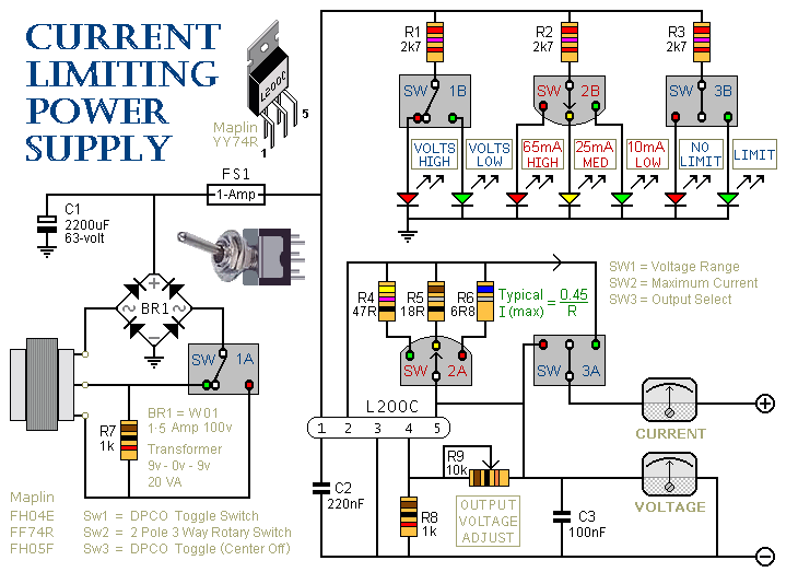
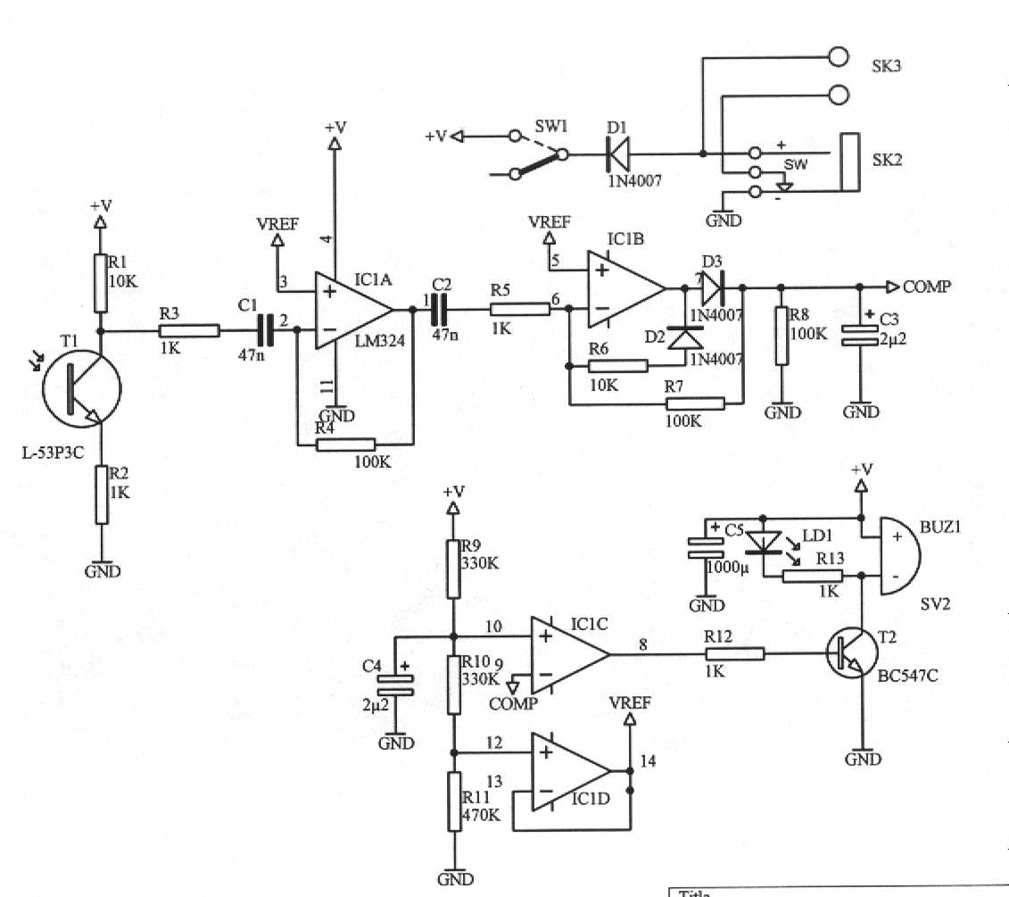
This is a 1-amp variable-voltage power supply unit (PSU) that adjusts the output voltage from approximately 3V to 24V. It features a current limiting option, which is particularly useful for initial power-ups or soak-testing equipment. SW3 acts as the...
This AC to DC power supply can output 5A in continuous operation and 12A peak current. This type of DC power supply uses a PCB, allowing for two case types. The described AC to DC power supply is designed to...
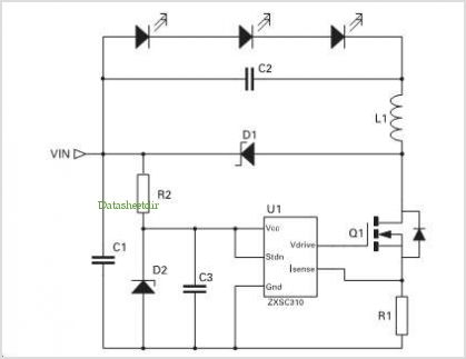
This is a basic flash memory programming voltage supply circuit. This circuit utilizes the LT1072 switching regulator to generate high voltage by driving the inductor L1 and resistor R2. The basic flash memory programming voltage supply circuit is designed to...
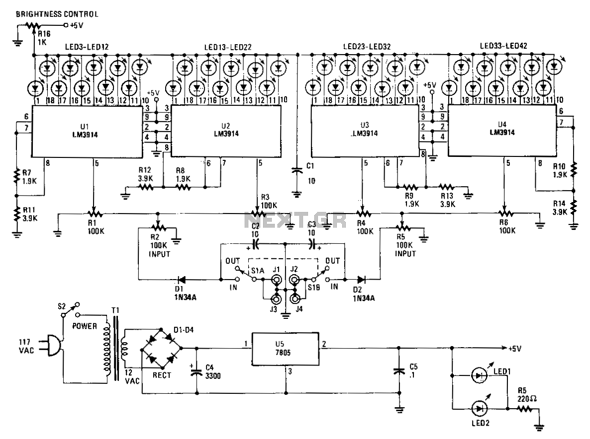
The Stereo Power Meter consists of two identical circuits and a power supply. Each circuit features two LM3914 display chips, which include 10 voltage comparators, a 10-step voltage divider, a reference voltage source, and a mode-select circuit that allows...
Application of the High Power LED Driver SP7652 with an Analog 0V-to-10V dimmer. Electrical Requirements: Input Voltage of 5.5V to 28V, Output Voltage VF of LED, Output Current ranging from 0 to 6A. This circuit is designed to provide...