
Best 12V battery charger circuit using LM311

This 12 Volt battery charger circuit is designed to efficiently charge lead-acid batteries while ensuring safety and longevity. The circuit typically consists of several key components, including a transformer, rectifier, voltage regulator, and control circuitry.
The transformer steps down the AC mains voltage to a lower AC voltage suitable for charging the battery. The rectifier, usually composed of diodes, converts the AC voltage to pulsating DC voltage. This DC voltage is then filtered to smooth out the ripples, providing a stable output.
A voltage regulator is integrated into the circuit to maintain a constant output voltage, preventing overcharging which can damage the battery. The control circuitry monitors the battery voltage continuously. When the voltage drops below a predetermined level, the circuit activates, allowing current to flow from the charger to the battery.
Additionally, the circuit may incorporate features such as an LED indicator to signal charging status and protection mechanisms like fuses or circuit breakers to prevent overcurrent situations. This design ensures that the charger operates safely and efficiently, extending the life of the battery being charged.
In summary, this automatic 12 Volt battery charger circuit is a reliable solution for maintaining battery health by providing controlled charging based on the battery's voltage level.The our best 12 Volt battery charger circuit, this is a charger circuit automatic system, then when the battery voltage is lower than specified, this circuit.. 🔗 External reference
Related Circuits
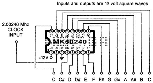
Using an MK50240, this circuit generates 12 top octave tones. The input and output lines can be separated using a binary divider IC to achieve the lower notes. Inputs and outputs are 12-volt square waves. The MK50240 is a specialized...
The main features of the MULTIWATT Package, a trademark of SGS-THOMSON Microelectronics, include a power amplifier IC designed specifically for car radio applications. It offers a high current capability of 3.5A and can drive a very low impedance of...
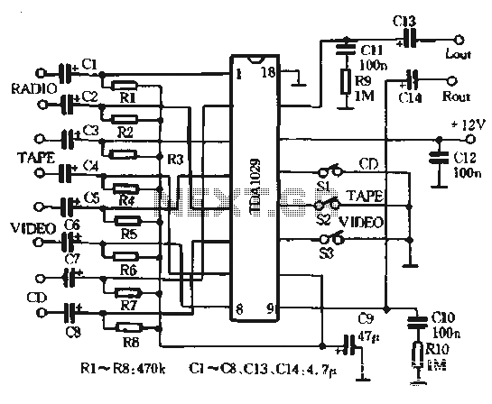
The AV combination as depicted in the diagram involves the first stage using the Philips TDA1029, which functions as a four-input switching signal processor. The second stage employs the NE5532 as a preamplifier, while the B of the NEC,...
The "R-h sampling circuit limit order" aims to reduce the sampling resistor. A DC voltage level can be positioned between the components. The circuit includes a line amplifier that allows for magnification adjustments and is designed to protect against...
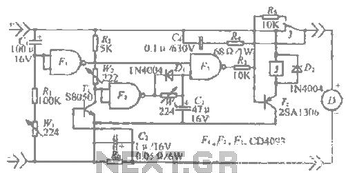
This is a 220V LED flasher circuit designed as a reliable alternative to thermally activated switches used for flashing Christmas tree lamps. It is a cost-effective and easy-to-assemble circuit. The components include R1 (100K), R2 (1K), R5 (1K), R3...
An integrated circuit is precisely that: an integrated circuit. These small packages combine numerous individual components to perform a specific function. They vary in shape and size depending on their complexity. They are categorized into functions such as audio,...