
Top Octave Generator Circuit

The MK50240 is a specialized integrated circuit designed for generating musical tones based on the principle of top octave synthesis. It provides a simple and effective means of producing a range of musical notes, typically used in electronic musical instruments and sound generation applications. The circuit operates by generating a series of square wave outputs corresponding to the top octave of a musical scale, which can be utilized in various sound synthesis applications.
In this circuit, the MK50240 generates 12 distinct square wave outputs, each corresponding to a different musical note in the octave. The outputs are typically at a frequency of 12 volts, suitable for driving further audio processing stages or directly interfacing with speakers. The generated tones can be used in synthesizers, alarms, or other electronic devices requiring sound output.
To obtain lower octaves from the output of the MK50240, a binary divider IC is employed. This IC divides the frequency of the square wave signals, allowing the user to access lower musical notes. By configuring the binary divider appropriately, it is possible to create additional octaves, enabling a broader range of musical expression.
The circuit design should include appropriate power supply decoupling to ensure stable operation of the MK50240 and the binary divider. Additionally, output filtering may be necessary to smooth the square wave signals if a more sine-like waveform is desired for specific applications. Overall, this circuit serves as an efficient solution for generating musical tones and can be adapted for various electronic sound synthesis projects. Using an MK50240, this circuit produces 12 top octave tones. The input and output lines can be divided using a binary divider IC to obtain the lower notes. Inputs and outputs are 12 volt square waves
Related Circuits
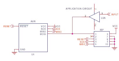
It is crucial to design the PCB layout correctly to enable seamless In-System Programming (ISP) of AVR microcontrollers. This guide addresses common issues encountered and provides typical AVR ISP circuit schematics. It focuses on Serial Programming, known as ISP,...
The circuit in Figure 1 converts pulse information to a clean dc voltage by the end of a single incoming pulse. In another technique, an RC filter can convert a PWM signal to an averaged dc voltage, but this...
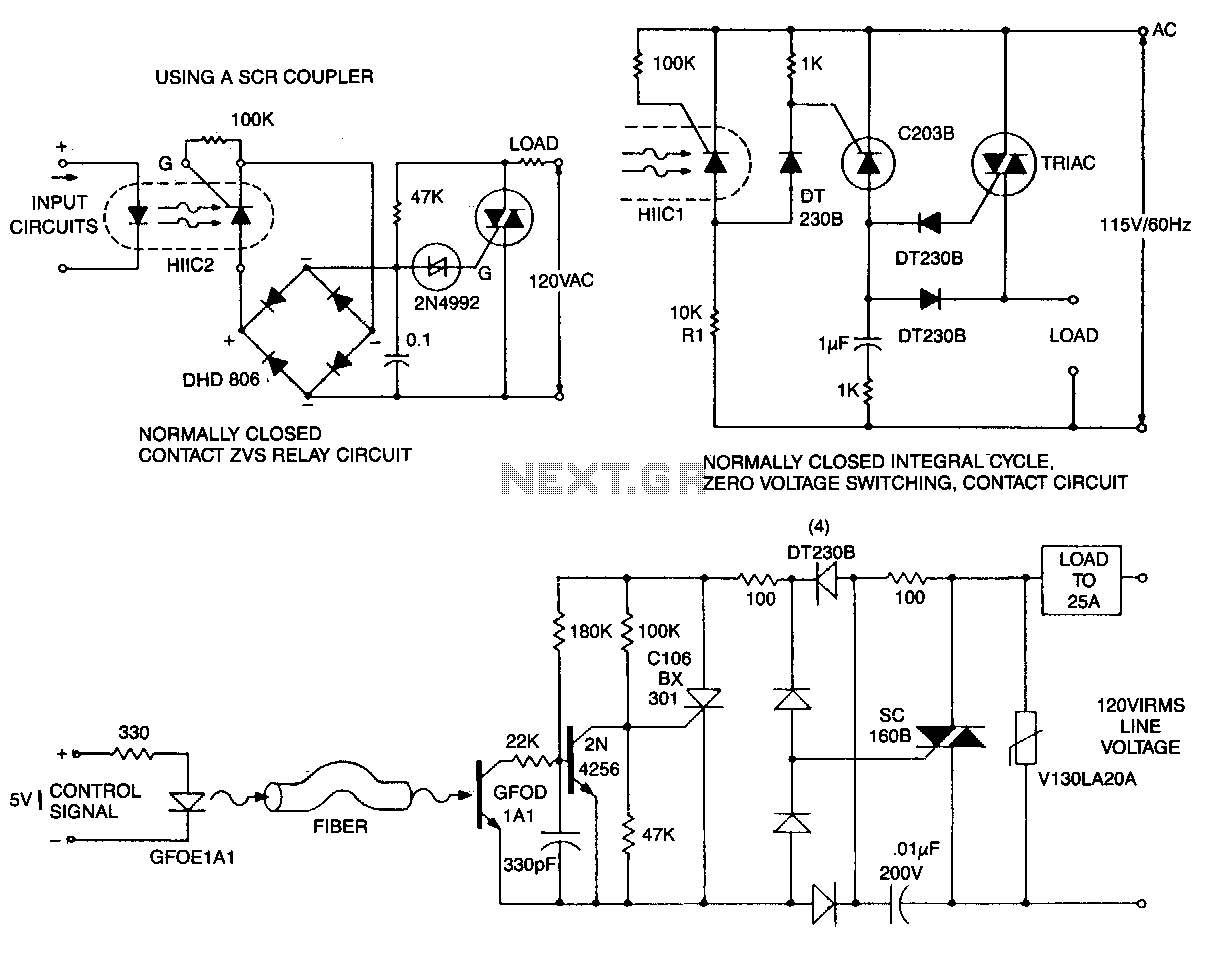
This circuit is effective for lamp and heater loads. Some circuits driving reactive loads require integral cycling and zero-voltage switching when an identical number of positive and negative half-cycles of voltage are applied to the load during a power...
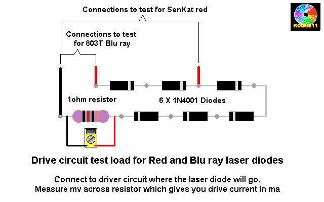
A guide will be posted on how to test a DDL circuit before integrating the LD. The process aims to ensure clarity and accuracy throughout. To properly test a DDL (Direct Drive Laser) circuit before adding the LD (Laser Diode),...
This high voltage converter circuit begins with a 30-volt power supply and is capable of delivering output voltages ranging from 0 to 3 kV for version 1, or from 0 to 10 kV for version 2. The high voltage converter...
This is a very simple crystal receiver circuit for short wave band and can be used with headphones. The described circuit is a basic crystal receiver designed to operate within the shortwave frequency band. The primary components of this circuit...