
Better-Sounding Active Crossovers

The presence of four transistors on the right-hand side of McBride's schematics typically indicates a specific function related to signal amplification, switching, or signal processing. In many electronic circuits, transistors serve as crucial components for controlling electrical signals.
In this context, the transistors may be configured in various arrangements such as common emitter, common collector, or common base configurations, each serving distinct purposes. For example, if they are arranged in a common emitter configuration, they could be used for signal amplification, where a small input signal can control a larger output signal. Conversely, if they are configured as switches, they may be utilized to turn on or off different parts of the circuit based on control signals.
Additionally, if these transistors are part of a differential amplifier configuration, they could be employed to amplify the difference between two input signals while rejecting any common-mode signals. This is particularly useful in applications where noise reduction is critical.
The specific function of these transistors can be further clarified by examining their connections to other components in the schematic, such as resistors, capacitors, and power supply lines. Understanding the overall circuit design and the role of each component will provide insights into the operation of the transistors and their contribution to the circuit's functionality.Hi, can anyone explain what the four transistors on the right hand side of each of McBride`s schematics are doing?.. 🔗 External reference
Related Circuits
The controller is quite simple. An input buffer ensures that the input impedance of the source does not affect the integrator performance and allows summing of left and right channels without any crosstalk. The output provides a phase reversal...
Nowadays every institution needs automation. As a part of college automation, a project has been developed for a Voice Interactive System for College Automation. This project allows users to quickly access student attendance and marks through the telephone line...
The problems that exist in common crossover networks are known. The low-pass filter causes delay in the signal. On the contrary, the high-pass filter causes a pre-ahead in the signal that it goes through from this. So, the cross-frequency...

A simple active mixer is desired to be placed in front of a power amplifier. Research has been conducted on active operational amplifier (op-amp) mixers, which provide various insights. An active mixer utilizing operational amplifiers (op-amps) is an essential circuit...
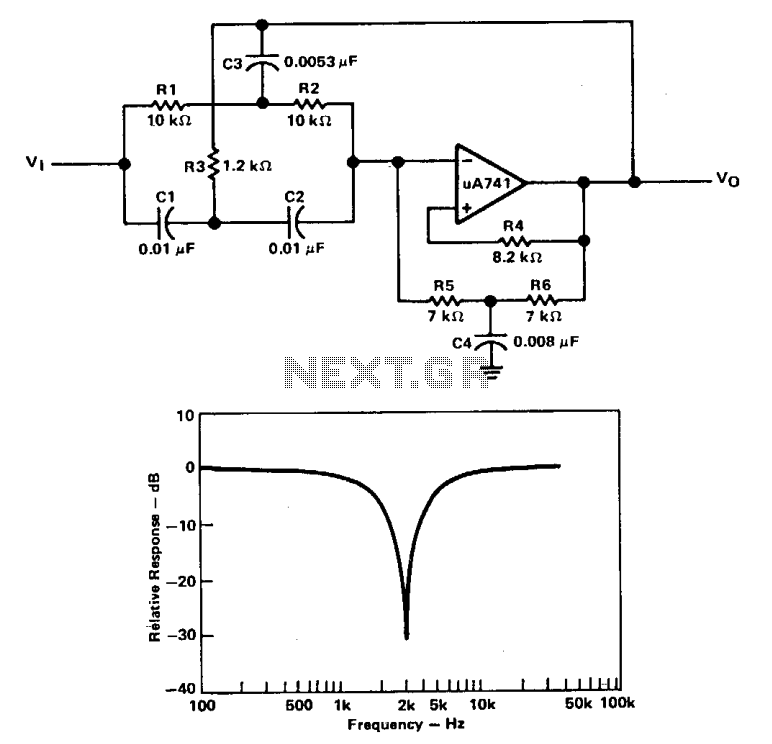
A filter with a band-reject characteristic is commonly known as a notch filter. A typical circuit employing a µ741 operational amplifier is shown in a unity-gain configuration for this type of active filter. The filter response curve illustrated represents...
Stationary - MOPLL & Silicon Tuner TUA6020 2 Band TV Tuner Mixer-Oscillator-PLL with balanced IF-Amplifier. The TUA6020 device integrates a digitally programmable Phase Locked Loop (PLL) with a mixer-oscillator block that includes two balanced mixers and oscillators suitable for...