
Active Crossover

Part List
R1-16=100Kohms R23-24-25-26=37.5Kohms [33K+4.7K] C12-13-20-21-22=1nF 100V MKT
R2-3-4-5=56Kohms R30-31-32-33-34-35-36=10Kohms C19-23-24-30-31-32-33=47nF 100V MKT
R6-27=37.5Kohms[33K+4.7K] R37-38-39-40-41-41=10Kohms C25-26-27-28-29=1nF 100V MKT
R8-9-12-13-14=10Kohms R42-43-44=47Kohms C36-37=1uF 100V MKT
R10-28=75Kohms (150K//150K) R45-46=47 ohms C38-39=47uF 25V
R11-29=NC TR1-2-3-4=47Kohms trimmer or pot. IC1=TL071
R15=56.3Kohms C1-34-35=2.2uF 100V MKT IC2-3-4-5-6-7=TL072-NE5532
R17=12Kohms C2-3-7-8-14-15-18=47nF 100V MKT
R18-19-20-21-22=10Kohms C4-5-6-9-10-11-16-17=10nF 100V MKT All the resistors are 1/4W 1% metal film.
The crossover circuit is constituted, as it appears from the block diagram, from two low-pass filters of fourth order -24dB/oct, one for the line of low-frequency signals and one for the high frequency. In the same frequency function, there are also two delay-time units, T1 (for low cross frequency F1) and T2 (for high cross frequency F2), which provide a characteristic phase with the low-pass part. The circuit delays T1 imitate the delay time that the low-frequency filter LPF1 imports, while T2 imitates the delay time that the low-frequency filter LPF2, which exists in the line of mid frequencies, imports. The signal that emanates from the low-pass filter is processed by IC7A-B, from the signal that has suffered delay, resulting in a signal that has characteristics similar to a signal that has passed through a low-pass filter. At the exit of each line, there is a trimmer that allows for adjusting the level and balance between the loudspeakers. The circuit is powered by a stabilized voltage of +/- 15V. The use of fourth-order Linkwitz crossover networks raises the cross-frequencies to -6dB.The problems that exist in common crossover networks are known. The low-pass filter causes delay in the signal. On the contrary the high-pass filter causes be pre-ahead in the signal that it in goes through from this. So, the cross-frequency are created certain problems as 1] the signals of two filters confutation 2] the change of phase between the filters influence axial 3]to axial diagram depend from the frequency.
The crossover circuit try it unties many from the problems that report above and are based on research of S. Lipshitz and J. Vanderkooy that was published in the magazine JAES (Journal Audio Engineering Society). A network crossover of linear phase it uses a low-pass department with the help of circuit of time delay and circuit of abstraction it gives in the exit signal with characteristically low-pass filter. This delay time is not constant for entire the area of frequencies, but is altered very late and mainly doesn't exist differences of phase between the signals of two outputs, neither even near in the cross-frequency.
Part List R1-16=100Kohms R23-24-25-26=37.5Kohms [33K+4.7K] C12-13-20-21-22=1nF 100V MKT R2-3-4-5=56Kohms R30-31-32-33-34-35-36=10Kohms C19-23-24-30-31-32-33=47nF 100V MKT R6-27=37.5Kohms[33K+4.7K] R37-38-39-40-41-41=10Kohms C25-26-27-28-29=1nF 100V MKT R8-9-12-13-14=10Kohms R42-43-44=47Kohms C36-37=1uF 100V MKT R10-28=75Kohms (150K//150K) R45-46=47 ohms C38-39=47uF 25V R11-29=NC TR1-2-3-4=47Kohms trimmer or pot. IC1=TL071 R15=56.3Kohms C1-34-35=2.2uF 100V MKT IC2-3-4-5-6-7=TL072-NE5532 R17=12Kohms C2-3-7-8-14-15-18=47nF 100V MKT R18-19-20-21-22=10Kohms C4-5-6-9-10-11-16-17=10nF 100V MKT All the rsestors is 1/4W 1% metal film.
The crossover circuit is constituted as it appears from block diagram [Fig.2] from two low-pass filters of fourth order -24db/oct, one for the line of low frequency signals and one for the high frequency. In the same frequency function also the two delay-time units, T1 (for low cross frequency F1) and T2 (for high cross frequency F2) and give him of characteristically phase with the low-pass part.
The circuit delays T1 imitate the delay time that import the filter of low frequencies LPF1, while the T2 imitates the delay time that import the filter of low frequencies LPF2 that exists in the line of mid frequencies. Then the signal that emanates from low-pass filter is removed with IC7A-B, from the signal that has suffered delay, result a signal that his characteristics is same with a signal that has passed in from a low-pass filter.
In the exit of each line found a trimmer with that we can adjust the level and level between the loudspeakers. The circuit supply become from a stabilized voltage +/- 15V. The use of crossover networks of fourth-order Linkwitz heaves the cross-frequencies to find in -6db [Fig.
3]. 🔗 External reference
Related Circuits
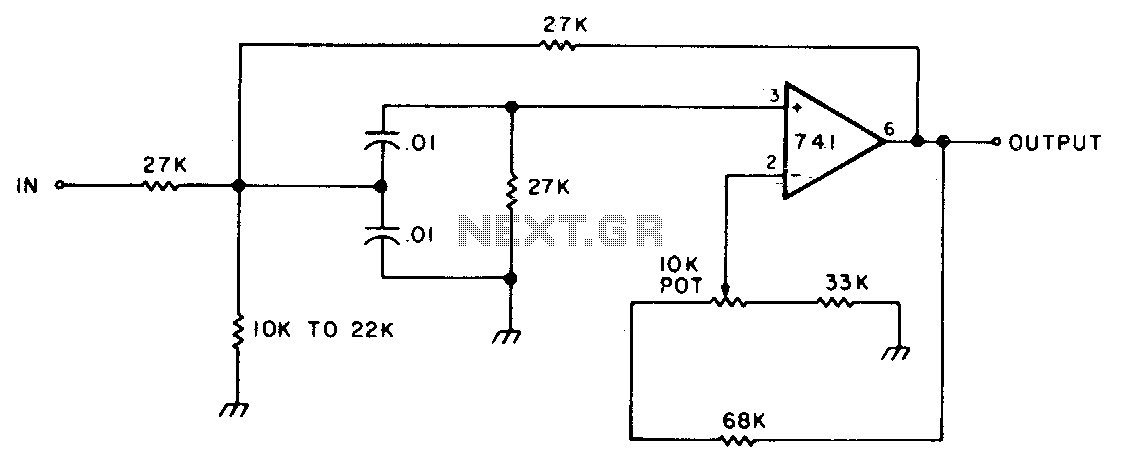
This circuit features adjustable bandwidth with a center frequency of approximately 800 Hz. A 10 kΩ potentiometer is used to adjust the bandwidth, varying from approximately ±350 Hz to ±140 Hz at the 3 dB down points. The circuit operates...
A Butterworth filter is a type of filter characterized by a frequency response that is flat within the passband region. This filter was first described by British engineer Stephen Butterworth. A Butterworth filter is designed to provide a maximally flat...
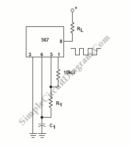
Unique applications of the 567 tone/frequency decoder IC include a pulse generator with a 25% duty cycle (active factor). This signal generator produces a specific output. The 567 tone/frequency decoder IC is a versatile component widely utilized in various electronic...
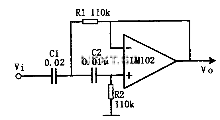
This document presents an active low-pass filter circuit with a cut-off frequency (fc) of 10 kHz. The circuit allows for various values for the ratios of resistors R1 and R2, as well as capacitors C1 and C2. Specifically, it...
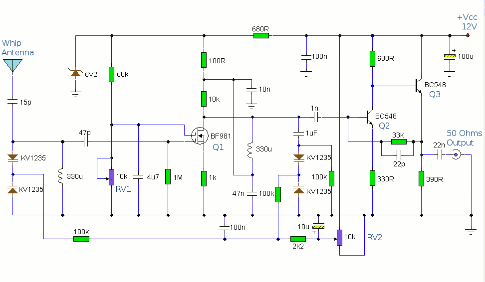
This circuit is designed to amplify the input from a telescopic whip antenna. The preamplifier is designed to cover the medium waveband from about 550KHz to 1650KHz. The tuning voltage is supplied via RV2, a 10k potentiometer connected to...
This simple filter utilizes an RC section as the filter element, incorporating a voltage follower to manage other frequencies. The -3 dB point is calculated as 1/(6.28 * RXCV), resulting in a response that drops 6 dB per octave...