
Bgb707l7esd As An Fm Radio Antenna Lna

The ATA6833-DK is designed specifically for controlling Brushless DC motors, which are widely used in various applications due to their efficiency and reliability. The Basic board integrates the ATA6833 and ATA6834, which serve as the gate drivers for the external MOSFETs. These components are crucial for managing the power delivery to the motor, enabling precise control of speed and torque.
The Controller board is equipped with the ATMEGA32M1 microcontroller, which is responsible for executing the control algorithms necessary for motor operation. It interfaces with the Basic board to send commands and receive feedback from the motor. The user interface on the Controller board allows for easy interaction, enabling users to adjust parameters such as speed, direction, and operational modes.
The temperature specifications are critical in selecting the appropriate chip for specific applications. The ATA6834, with its higher tolerance for heat, is particularly advantageous in environments where the motor may be subjected to elevated temperatures, such as automotive applications. In contrast, the ATA6833 is suitable for applications with lower thermal requirements.
Overall, the ATA6833-DK kit provides a comprehensive solution for developers looking to implement BLDC motor control in various applications, ensuring both flexibility and performance through its robust design and component selection.This document provides details on using the ATA6833-DK for BLDC Motor Control applications. The BLDC Motor Control Kit consists of two boards: Basic board with a BLDC Gate Driver SBC (System Basis Chip) ATA6833 ATA6834 and external MOSFETs Controller board with a Microcontroller ATMEGA32M1 and a user Interface The temperature ran ge is the primary difference between the ATA6833 and ATA6834. The maximum junction temperature of 200 °C allows designing under-the-hood appli- cations with the ATA6834 while the maximum junction temperature of the ATA6833 is 150 °C. If not otherwise stated, the ATA6833 stands for the two of the devices. 🔗 External reference
Related Circuits
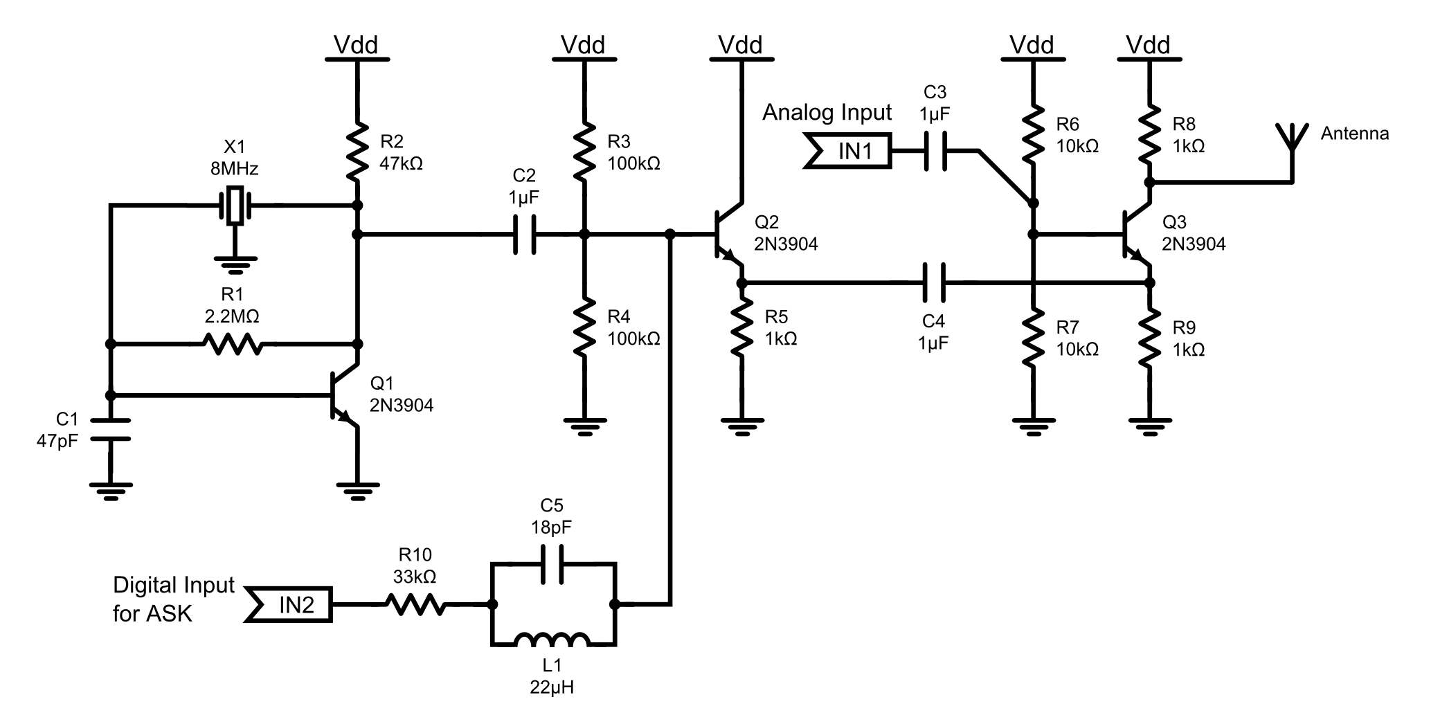
This is an 8MHz amplitude modulated (AM) radio transmitter designed primarily for practical applications and as an educational exercise in electronics. The objective was to create a simple radio transceiver that could be used in future projects requiring basic...
This technique eliminates the need for an additional cable to power the FM antenna amplifier. The RF signal and the DC current that supplies the amplifier utilize the same cable simultaneously. An FM antenna booster circuit diagram can be...
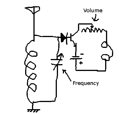
This circuit allows the selection of a station by adjusting the capacitance in an LC circuit. However, the signal remains modulated. To demodulate the signal, a second capacitor is required, but the function of this component is unclear. The...
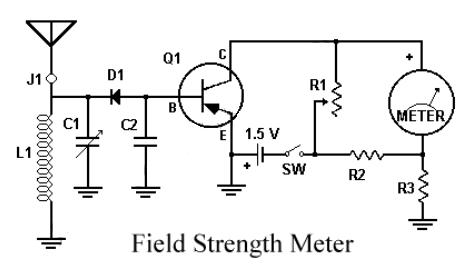
This circuit utilizes a single 1.5V battery. The capacitor C1 must be adjusted for optimal peak reading. To operate the circuit, the transmitter and meter should be turned on. The circuit is designed to operate efficiently with a single 1.5V...
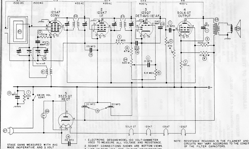
"Black Beauty" is a nickname for a classy Bakelite radio set. It features a dramatic, asymmetrical design with deep wraparound louvers and a bullet-like profile, exemplifying 1940s Streamline design. The radio is undergoing restoration of its electronics and cabinet....
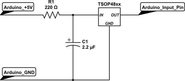
To set up the circuit, a resistor is required; a value of 200 Ohms is suggested, with a supply voltage of 3.3V. The resistor should be connected to the power line and grounded. The data line must be connected...