
How should I wire up the circuit to connect a TSOP4838 (Radio Shack 276-64) infrared receiver to an Arduino
 infrared receiver to an Arduino")
To implement this circuit effectively, it is essential to ensure proper connections and component selection. The 200 Ohm resistor serves to limit the current flowing into the data line, protecting the microcontroller from potential damage due to excessive current. When using a 3.3V supply, the resistor should be connected between the power line and the data line, with the other end of the data line connected to a digital pin, such as pin #2 on the Arduino.
In the example provided in the datasheet, the inclusion of a 100 Ohm resistor and a 4.7 microfarad capacitor suggests a design consideration for stability and noise reduction. The capacitor acts as a filter, smoothing out fluctuations in the power supply and providing transient response improvements. When connecting Vs to the 3.3V output of the Arduino, it is advisable to include the capacitor to ensure stable operation, especially if the circuit will be subjected to varying loads or if the data line experiences high-frequency switching.
The circuit schematic should clearly represent these connections: the 200 Ohm resistor in series with the data line, the capacitor connected in parallel between Vs and ground, and the digital pin connection. Proper labeling of components and values on the schematic will facilitate understanding and implementation. Additionally, if the design experiences issues with signal integrity or stability, experimenting with different capacitor values may yield beneficial results.All you need to do is supply a resistor (I used 200 Ohms, with a 3. 3V supply) to the power line, GND it, then connect the data line to one of your digital pins (I used pin #2)". However, the datasheet shows an example circuit with a 100 Ohm resistor connected to Vs along with a 4.
7 micro Farad capacitor connected between Vs and GND. I`m guessing that I should connect Vs to the 3. 3V output on the Arduino and use a 200 Ohm resistor, but do I need a capacitor 🔗 External reference
Related Circuits
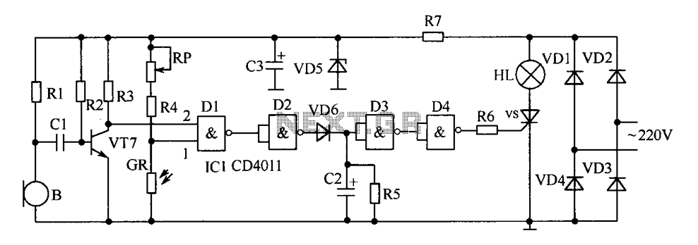
The delay-saving lamp circuit functions as a sound and light control delay energy-saving lighting system. It can directly replace a standard light switch without modifying the existing lighting circuits. In bright or daytime conditions, the sound control feature ensures...
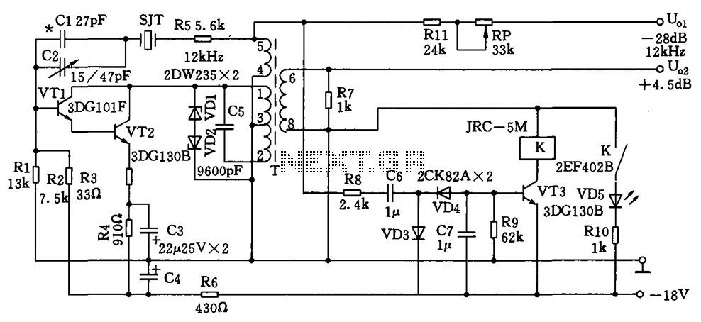
The circuit depicted is a 12 kHz intermediate frequency oscillator designed for an alarm system. It employs a variable feedback oscillation circuit where the oscillation frequency is primarily determined by a quartz crystal. Capacitors C1 and C2 are used...

This simple circuit consists of a transformer, two diodes, a capacitor, and an ammeter. To charge a battery, connect the positive and negative terminals of the circuit to the corresponding terminals of the battery. When the battery is not...
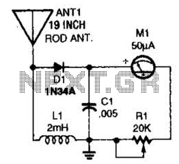
This basic field-strength meter offers an affordable solution for monitoring an amateur radio or CB transmitter, as well as an antenna system, to ensure maximum output. The field-strength meter is designed to measure the strength of radio frequency (RF) signals...
This is an upgraded circuit based on the Simple Volume Unit Display Circuit Diagram 1, featuring enhanced power for the audio input. Components include resistors. The upgraded circuit enhances the functionality of the original Simple Volume Unit Display by incorporating...
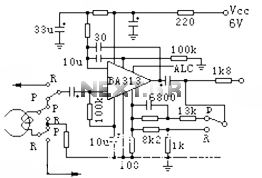
The BA313 is an integrated automatic level control (ALC) circuit designed for use in audio recording preamplifier applications. It is commonly found in cassette tape recorders and comes in a 9-pin dual in-line package (DIP). The circuit features a...