
Bi-Directional Motor Control CIrcuit With NE555 IC

The bi-directional motor control circuit designed with the NE555 IC allows for efficient control of a DC motor's direction and speed. The circuit operates on a 12V DC power supply, which is a common voltage level for many small to medium-sized motors.
The NE555 timer IC is configured in astable or monostable mode, depending on the specific application requirements. In this setup, the NE555 generates a PWM (Pulse Width Modulation) signal, which can be adjusted to control the speed of the motor. The output from the NE555 drives a relay (RL1), which acts as a switch to control the direction of the motor.
The circuit typically includes two relays (RL1 and RL2) to facilitate the bi-directional operation. By energizing either relay, the current flow through the motor is reversed, allowing the motor to rotate in either direction. Diodes are often included across the relay coils to prevent back EMF from damaging the NE555 when the relays are de-energized.
Additional components may include resistors and capacitors that set the timing characteristics of the NE555, as well as potentiometers for adjusting the motor speed. The design is suitable for applications such as robotics, conveyor systems, and any project requiring precise motor control.
Safety features may also be integrated into the circuit, including fuses and thermal cutoffs, to protect against overcurrent conditions. Overall, this bi-directional motor control circuit is a versatile solution for various motor control applications.This circuit shows about Bi-Directional Motor Control CIrcuit With NE555 IC. Features: 12V DC power supply, IC is used to control the relay RL1 .. 🔗 External reference
Related Circuits
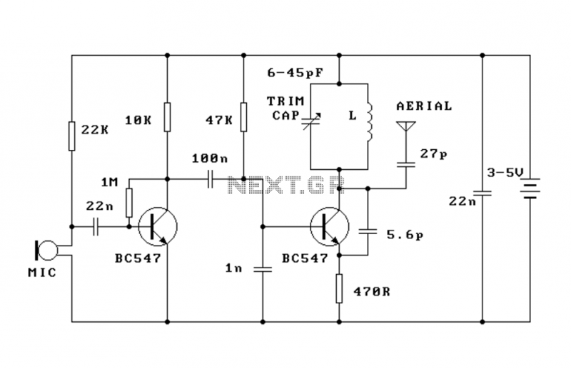
This FM transmitter (FM Tx) is about the simplest and most basic FM Tx it is possible to build and have a useful transmitting range. It is surprisingly powerful despite its small component count and 3V operating voltage. It...
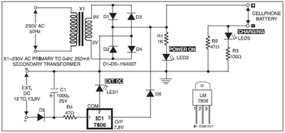
The 220V AC mains supply is downconverted to 9V AC by transformer X1. The transformer output is rectified by diodes D1 through D4 wired in bridge configuration, and the positive DC supply is directly connected to the charger's output...
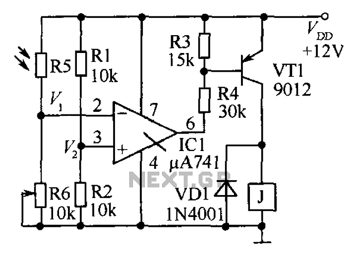
The circuit functions as a precision bright light control circuit, operating independently of power supply voltage and ambient temperature. Resistors R1, R2, R6, and the photosensitive resistor R5 form a two-arm Wheatstone bridge. The precision bright light control circuit utilizes...
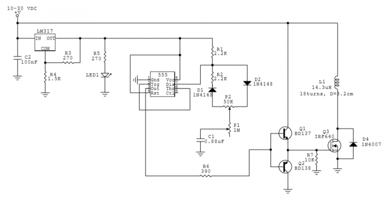
This circuit utilizes a 555 Integrated Circuit (IC) to generate a pulsed magnetic field, which can be employed for pulsed electromagnetic field (PEMF) therapy. The human body is affected by natural magnetic fields, including the Earth's magnetic field, geomagnetic...
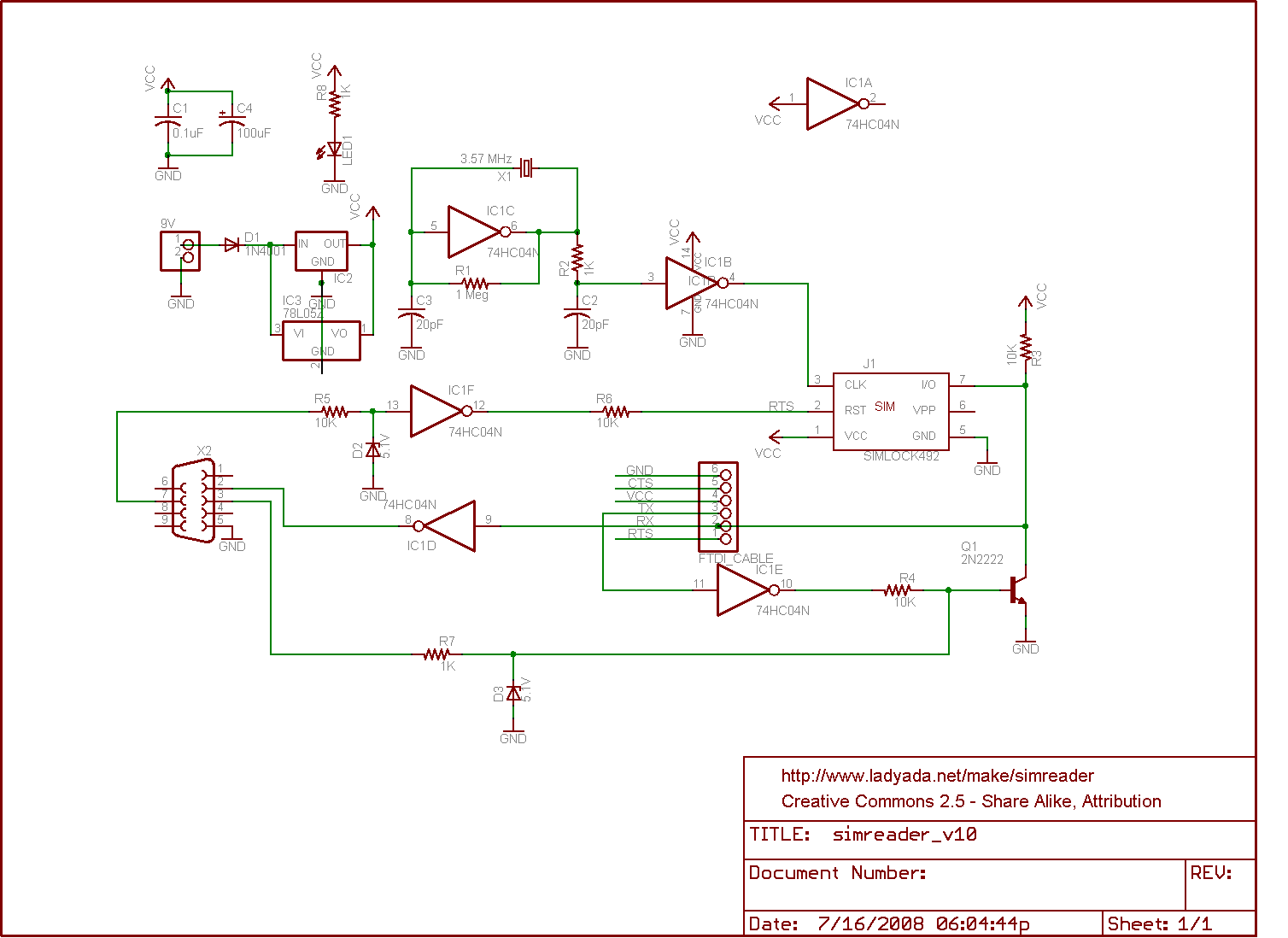
The circuit for a SIM card reader is presented here. It utilizes a CMOS hex inverter along with other basic components. Not only does it function effectively, but it is also capable of communicating with a PC through a...

This automatic light dimmer circuit enables controlled lighting that gradually turns on or off. The operation is as follows: when switch S1 is closed, capacitor C1 charges slowly. Once the voltage across C1 reaches 0.6 volts, transistor T1 begins...