
Bright light control circuit diagram of a precision

The precision bright light control circuit utilizes a Wheatstone bridge configuration to achieve stable performance regardless of variations in power supply voltage and environmental conditions. The primary components include resistors R1, R2, R6, and the photosensitive resistor R5.
In this configuration, the two-arm Wheatstone bridge is designed to measure the resistance changes in the photosensitive resistor R5, which varies with light intensity. When light levels increase, the resistance of R5 decreases, causing an imbalance in the bridge circuit. This imbalance generates a voltage difference that can be used to control an output device, such as a light dimmer or an automatic lighting system.
Resistors R1 and R2 are typically fixed values that help set the reference voltage levels for the bridge, while R6 can be adjusted to calibrate the sensitivity of the light detection. The circuit is designed to maintain a consistent output signal, ensuring that fluctuations in supply voltage or temperature do not affect the performance of the light control mechanism.
This circuit is particularly useful in applications where precise light control is necessary, such as in photography, horticulture, or automated lighting systems, where maintaining consistent light levels is critical for optimal performance. As shown in the circuit as a precision bright light control circuit, its work is not affected by the power supply voltage and ambient temperature. Resistors R1, R2, R6 and phot osensitive resistance R5 together constitute two-arm Wheatstone bridge.
Related Circuits
The layout control motherboard is designed to facilitate the management of various sections of a layout. It features a microcontroller that connects to the MRNet bus and multiple slots for inexpensive control and sensor boards. All control and sensor...
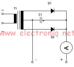
This simple lead-acid battery charger requires a center-tapped transformer (12V 0V 12V) capable of delivering a current of 5 amperes, two diodes, and one capacitor. To charge the batteries, the positive and negative terminals from the charger must be...
This document outlines a battery monitoring circuit designed to measure the voltage of 12V lead-acid batteries, such as those used in automobiles. The circuit utilizes the LM3914 integrated circuit (IC) along with several external components, including a series of...
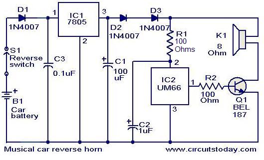
This circuit is designed to produce a musical horn whenever a car is in reverse gear. It utilizes two integrated circuits (ICs) for its operation: a voltage regulator (7805, referred to as IC1) and a musical tone generator (UM66,...
The use of diode rectifiers in AC voltmeters with a low lower limit of measurement range (0.5-1 V) leads to significant nonlinearity of the scale due to the nonlinearity of the current-voltage characteristics of diodes. The incorporation of electronic...
Replacing the LC modulation circuit with an active filter allows for the elimination of large and costly inductance coils in frequency shift key control demodulators. This approach not only reduces the size of the circuit but also enhances the...