
Bi-Stable Multivibrator (RS Flip-FLop) with Op-Amp
 with Op-Amp")
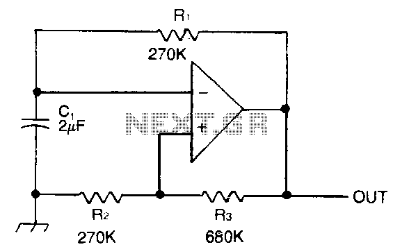
The bi-stable circuit described operates using an operational amplifier (op-amp) configured to function as a flip-flop. The two stable states of the circuit are maintained through positive feedback, allowing the circuit to retain its output state until an external input triggers a change. The circuit consists of an op-amp, resistors, and capacitors arranged in such a way that the output voltage can switch between two distinct levels, typically representing binary states.
In this configuration, the non-inverting input of the op-amp is connected to a voltage divider formed by two resistors. The inverting input is connected to the output through a feedback resistor, creating a loop that reinforces the current state of the output. When a trigger signal is applied to the non-inverting input, the op-amp responds by changing its output state, which in turn affects the feedback loop and stabilizes the new state.
The circuit can be reset or set by applying appropriate signals to designated inputs, allowing for versatile applications in digital electronics, such as memory storage, frequency division, and signal conditioning. The response time and stability of the circuit can be adjusted through the selection of resistor and capacitor values, enabling fine-tuning for specific applications. The bi-stable nature of this circuit makes it ideal for use in applications requiring memory elements or state retention without continuous power supply.This bi-stable circuit uses an op-amp, acts similar with RS flip-flop. Bi-stable circuit is a circuit with two stable states, low and remain low until set is.. 🔗 External reference
Related Circuits
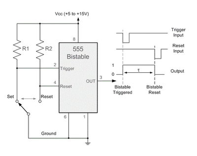
By applying a "LOW" signal to the Trigger input (pin 2) while the switch is in the Set position, the output state changes to "HIGH". Conversely, applying a "LOW" signal to the Reset input (pin 4) while the switch...
The circuit does not fail under slight variations, even if the input/output electric current characteristics are exceeded. Failure occurs only during a short circuit or extreme conditions at the output. The operation of the circuit is explained as follows:...
An astable multivibrator is a flip-flop that produces two unstable states (high and low), functioning as an oscillator. An astable multivibrator is a fundamental electronic circuit that continuously switches between its two states without requiring any external triggering signals....
Capacitor C1 is charged through timing resistor R1 when the clock output is high. When C1 reaches the upper threshold voltage, the output signal decreases, and then C1 discharges through R1 until its voltage reaches the lower threshold point....
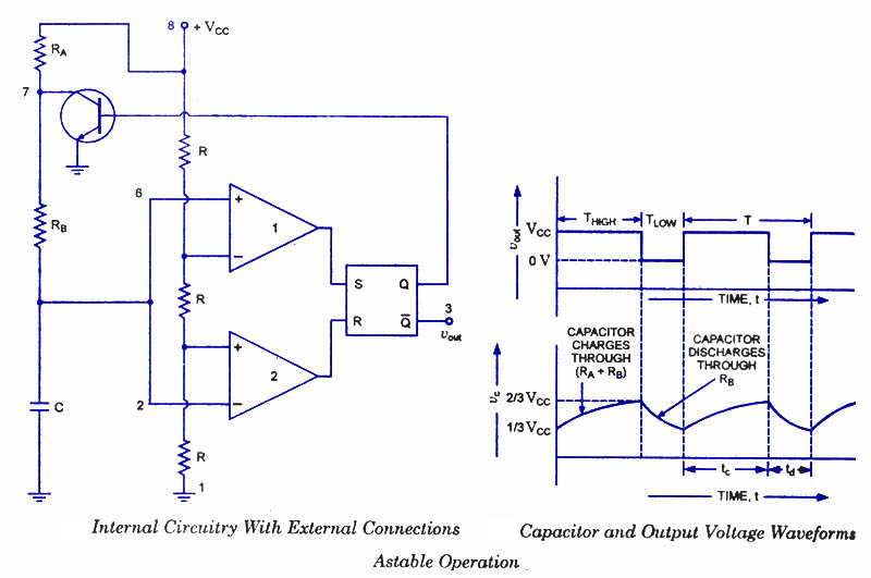
An astable multivibrator, often referred to as a free-running multivibrator, is a rectangular-wave generating circuit. Unlike the monostable multivibrator, this circuit does not require any external trigger to change the state of the output, hence the term free-running. Before...
Voltage to frequency conversion is highly beneficial in various applications, such as transmitting temperature measurements using standard voice radio transceivers. This circuit utilizes two CA3130 operational amplifiers, demonstrating satisfactory performance. The linearity of the voltage-frequency transfer is better than...