
bistable multivibrator using ic 555

The 555 timer in bistable mode operates as a flip-flop, allowing it to store a binary state. In this configuration, the circuit utilizes two primary inputs: the Trigger and Reset. The Trigger input (pin 2) is activated by a negative edge signal. When this pin receives a "LOW" signal, it causes the output (pin 3) to switch to "HIGH", indicating that the circuit is in the Set state. The Reset input (pin 4) serves a complementary function; when it is pulled "LOW", it resets the output to "LOW", placing the circuit in the Reset state.
The bistable configuration of the 555 timer is particularly useful in applications requiring stable states, such as memory storage, toggle switches, or state retention in digital logic systems. The device remains in its current state until an appropriate input signal is applied, ensuring it does not change states accidentally due to noise or fluctuations in the input signals.
The timing characteristics of the 555 timer in this mode are determined by external components connected to the circuit, such as resistors and capacitors, which can influence the response time and stability of the output states. However, in its basic bistable operation, the 555 timer is capable of maintaining its output state without the need for continuous input signals, making it a reliable choice for various electronic applications.By taking the Trigger input (pin 2) "LOW", switch in Set position, changes the output state into the "HIGH" state and by taking the Reset input (pin 4) "LOW", switch in Reset position, changes the output into the "LOW" state. This 555 timer circuit will remain in either state indefinitely and is therefore bistable. Then the Bistable 555 timer is s table in both states, "HIGH" and "LOW". 🔗 External reference
Related Circuits

Utilize a PIC Microcontroller to Control a Hobby Servo. This guide outlines the process of incorporating hobby servos, typically found in remote-controlled airplanes, cars, and similar devices. To implement the control of a hobby servo using a PIC microcontroller, the...
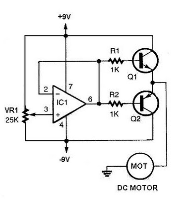
The speed increases in either direction as the potentiometer VR1 is adjusted toward its ends. The TIP3055 Q1 NPN power transistor has a collector current specification of 15A and a VCE0 rating of 60V DC. The MJE34 Q2 PNP...
Temperature sensor converter designed for use with a digital multimeter, capable of measuring temperatures from -40 °C to 110 °C. It features a state indicator and requires no calibration, utilizing the LM35 integrated circuit. The freezing point of water...

The project involves SMS control for older Nokia phones using the FBUS protocol, which is a complex communication method requiring detailed understanding and coding. The author has successfully implemented this project using an 89S52 microcontroller with only 256 bytes...

The SN74AVCA406E is a transceiver designed for interfacing microprocessors with MultiMediaCards (MMCs), secure digital (SD) cards, and Memory Stick compliant products. It is manufactured by Texas Instruments. The SN74AVCA406E transceiver is a versatile device that facilitates communication between microprocessors and...
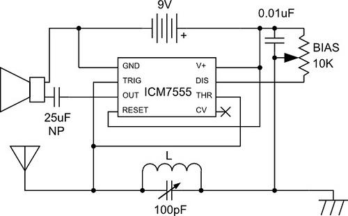
An AM radio is constructed using a 555 timer chip as the sole active component. The tuning mechanism consists of an inductor and a capacitor, while the LM555 functions as an AM demodulator and a class-D power amplifier to...