
Bias Supply For Microwave Preamps

The circuits described are essential for ensuring proper biasing of microwave preamplifiers, which are crucial in high-frequency applications. The passive supply in Figure 51-5(a) typically consists of resistors and capacitors that provide a stable voltage to the preamp. This method is straightforward and cost-effective, but it may not offer the precision required in high-performance applications.
In contrast, the active supplies illustrated in Figures 51-5(b) and 51-5(c) employ more complex circuitry to achieve better regulation of the supply voltages. The component Ul is responsible for generating a negative voltage supply, which is often necessary for the operation of certain types of microwave preamps that require a negative bias. The use of an active component allows for improved voltage stability over varying load conditions compared to a passive supply.
Moreover, the transistor Ql plays a crucial role in these active circuits by controlling the drain voltage and current. This configuration allows the circuit to maintain consistent performance regardless of variations in the GASFET characteristics, such as threshold voltage and transconductance. By isolating the biasing conditions from the GASFET's inherent properties, the design enhances the overall reliability and performance of the microwave preamplifier.
In summary, the combination of passive and active biasing circuits provides flexibility in designing microwave preamp systems, allowing engineers to select the most appropriate method based on performance requirements and application constraints. These two circuits provide bias for the microwave preamps shown in this text. The circuit in Fig. 51-5(a) is a simple passive supply. Figures 51-5(b) and 51-5(c) are active supplies, with Ul generating a negative supply and Ql setting the drain voltage and current, independent of GASFET characteristics.
Related Circuits
Many modern circuits operate from a single supply voltage of 3V. However, they often require a virtual ground at half the supply voltage for optimal performance. The splitter depicted in the diagram divides the supply voltage using a high-resistance...
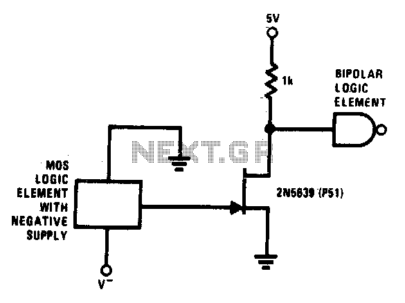
This simple circuit facilitates level shifting from any logic function (such as MOS) operating from a negative to ground supply to any logic level (such as TTL) operating from a positive to ground supply. The 2N5639 transistor offers low...
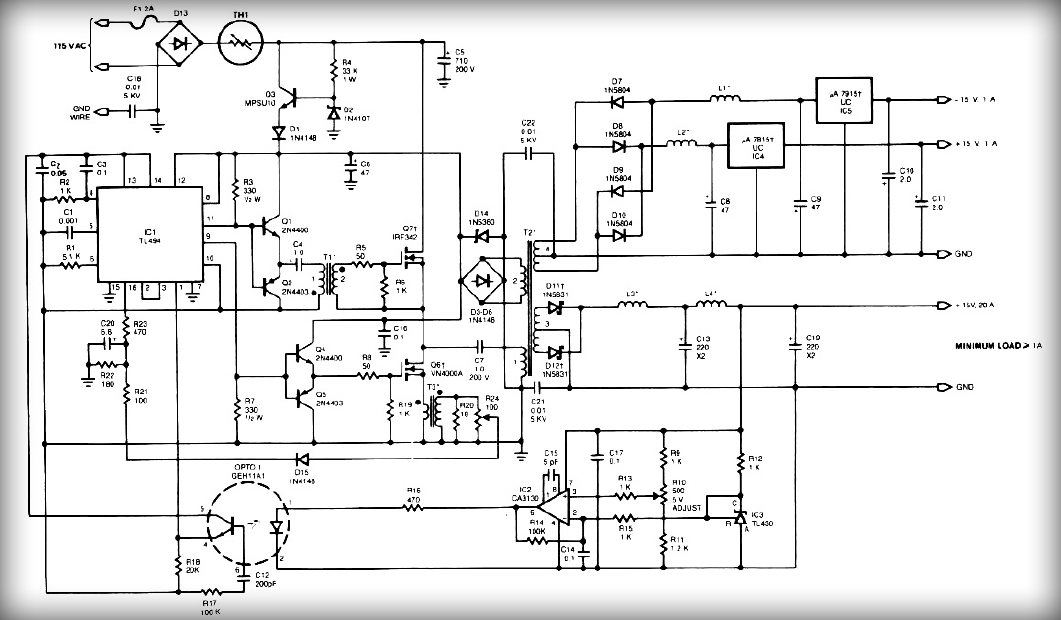
This power supply employs two VN400A 400-Volt MOSFETs arranged in a half-bridge configuration. The outputs provide +5V at 20A and +15V at 1A. Low-current outputs utilize three-terminal regulators, allowing for either 12 Volts or 15 Volts to be achieved...
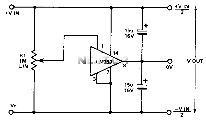
This circuit employs the quasi-complementary output stage of the well-known LM380 audio power integrated circuit (IC). The IC is internally biased to maintain the output at a midpoint between the supply rails when there is no input signal. A...
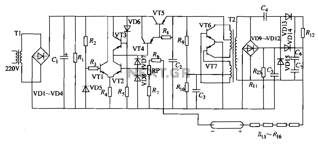
The DC power supply is a helium-neon laser excitation power supply, which is currently the most commonly used type of power supply. It is utilized in laser printers. The circuit includes a power transformer (T1), a high-voltage transformer (T2),...
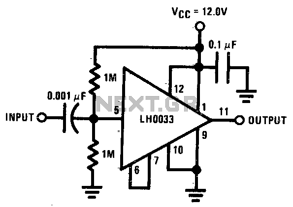
The input is DC biased to the mid-operating point and is AC coupled. Its input impedance is approximately 500K ohms at low frequencies. For DC loads referenced to ground, the quiescent current is increased by the load current set...