
Negative to positive supply logic level shifter

The described circuit is essential for interfacing different logic families, particularly when there is a need to translate signals between devices operating at different voltage levels. The use of the 2N5639 transistor is notable due to its favorable electrical characteristics, which include low on-resistance (R_on) that minimizes power loss during operation and enables efficient signal transmission.
In practical applications, the circuit typically includes input and output terminals for connecting to the respective logic devices. The input side would be connected to a MOS logic device that operates with a negative voltage supply, while the output side interfaces with a TTL logic device that operates with a positive voltage supply.
The level shifting mechanism can be achieved through a simple configuration where the 2N5639 is configured as a common-emitter amplifier or as a switch, depending on the specific requirements of the application. Resistors may be added to control the base current of the transistor and to set the appropriate biasing conditions, ensuring that the transistor operates efficiently within its active region.
Additionally, capacitors might be included for decoupling purposes, helping to stabilize the power supply and filter out noise that could affect the performance of the circuit. The overall design should ensure that the voltage levels are appropriately translated without distortion, maintaining signal integrity across the different logic families.
This level-shifting circuit is particularly valuable in mixed-signal applications, where integration of analog and digital components necessitates reliable communication across varying voltage domains.This simple circuit provides for level shifting from any logic function (such as MOS) operating from minus to ground supply to any logic level (such as TTL) operating from a plus to ground supply The 2N5639 provides a low r«: (on) and fast switching times.
Related Circuits
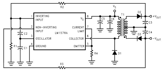
This RS232 power supply circuit diagram is a simple RS-232 line driver power supply that operates from an input voltage as low as 4.2V and delivers an output of ±12V at ±40 mA with an efficiency of better than...
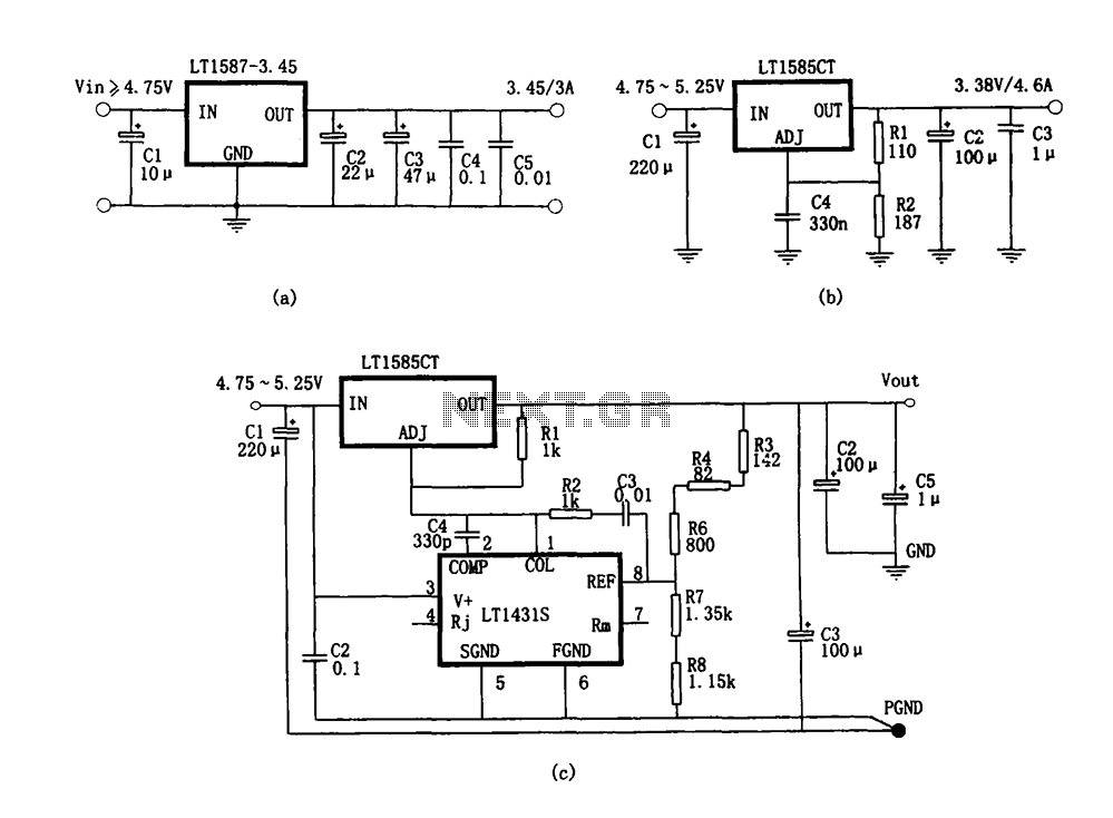
Figure (a) illustrates a microprocessor power supply circuit utilizing the LT1587-3.45. Figure (b) depicts a power supply with an adjustable output voltage constructed using the LT1585. Figure (c) showcases a computer power supply circuit formed with the LT1584 and...
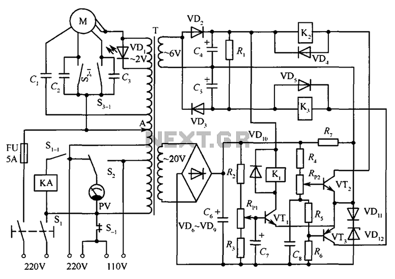
The circuit illustrated in the figure features an automatic voltage regulator (T) that utilizes a servo motor to ensure a constant output voltage. The transistors used are VT1 and VT2 (3DK9C, with a range of 65 to 85) and...
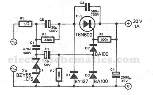
This transformerless power supply circuit is designed for medium current applications. During the negative half period, the capacitor C5 is charged to the peak voltage of the network. The positive half wave will trigger the thyristor, allowing the electric...
This water level sensor circuit utilizes a standard NAND logic gate to generate oscillation and detect water levels. The oscillation functionality is integrated within the circuit. The water level sensor circuit employs a NAND logic gate to create a square...
This circuit is a simple form of the commercial UPS, the circuit provides a constant regulated 5 Volt output and an unregulated 12 Volt supply. In the event of electrical supply line failure the battery takes over, with no...