
stepper motor interfacing with spartan 3 primer

The Spartan-3 Primer board is designed to facilitate the integration of stepper motors into various applications. The ULN2803A serves as an essential component in this setup, allowing for the control of multiple stepper motors through a single interface. The Darlington transistor array is capable of handling high voltages and currents, making it suitable for driving motors that require significant power.
The port I/O lines from the Spartan-3 FPGA connect to the input pins of the ULN2803A. This configuration enables the FPGA to send control signals to the motor, allowing for precise movement and positioning. Each output pin of the ULN2803A corresponds to a specific control line for the stepper motor, which can be sequenced to achieve the desired rotation direction and speed.
The inclusion of the PTB connector offers flexibility in power supply options. For applications that require higher power than what the board can provide, an external power source can be connected through this connector. This feature ensures that the stepper motor receives adequate power for operation, thereby enhancing the overall performance of the system.
In summary, the Spartan-3 Primer board, with its ULN2803A driver and PTB connector, provides a robust solution for interfacing with stepper motors, making it suitable for various projects that involve motion control and automation. This configuration not only simplifies the design process but also enhances the reliability and efficiency of motor control applications.The Spartan-3 Primer board has external stepper motor interfacing, indicated as in Figure. Stepper Motor is driven by ULN2803A. It is a high-voltage, high-current Darlington transistor array. ULN2803 is used as a driver for port I/O lines, drivers output connected to stepper motor, PTB connector provided for external power supply if needed. 🔗 External reference
Related Circuits
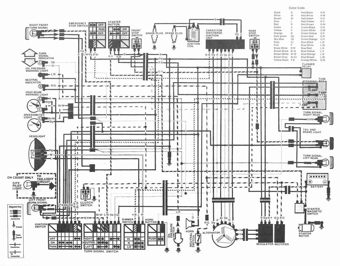
The following image depicts the electrical wiring connection diagram for the Honda Motorcycle CB400 (Hawk II). It illustrates the interconnections between various Honda components, including the turn signal, emergency stop switch, starter button, spark plug, capacitor discharge ignition unit,...

An issue with CPLD and FPGA devices is that they have numerous I/O pins, resulting in schematics that quickly become overwhelmingly large. Different sections of the schematic have been partitioned to illustrate the motor control circuit, analog-to-digital converter circuit,...
The resistors R18 and R22, which were intended to be connected to pin 8 of U4, were incorrectly connected to pin 9. The current versions have been corrected. There is a minor error in the component layout where two...
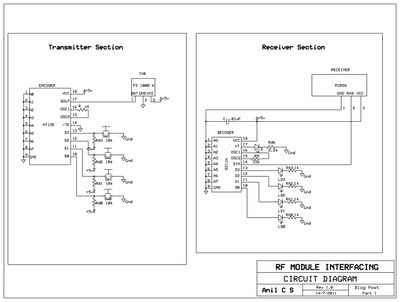
This document presents a circuit example for interfacing an RF module using the HT12E/D encoder-decoder pair. The attached circuit can be utilized for data transmission via the RF module, which is designed for single-channel operation, allowing only serial data...
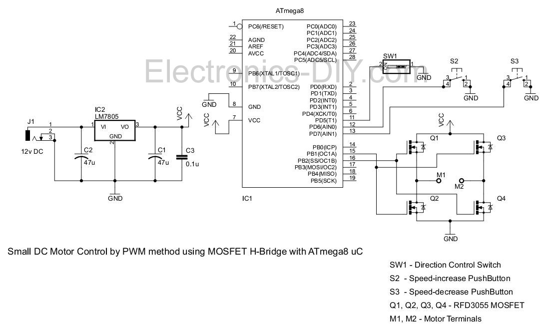
This project involves controlling a small DC motor, sourced from an old personal cassette player, using the ATmega8 microcontroller. The ATmega8 features three PWM channels, of which two are utilized in this application. The PWM signals are sent to...
The circuit illustrated in the schematic diagram below allows for the visualization of the direction and shaft rotation of a stepper motor on an LED display. Instead of utilizing a digital rotation encoder as an input, this circuit employs...