
Big Trak Motor Driver Schematic

The motor driver circuit for the Big Trak toy is designed to facilitate the control of the motors that drive its movement. The primary component responsible for motor control is the 75494 integrated circuit, which functions as a quad latch. However, due to its limited current output capabilities, additional transistors are employed to enhance the circuit's performance.
The 9112 and 9113 transistors are typically used in this configuration. These transistors serve as switches, allowing the 75494 chip to control the larger currents required by the motors without being overloaded. In some instances, the 2N6715 transistor may also be utilized, providing an alternative option that can handle higher current levels, thus ensuring reliable motor operation.
The circuit operates by sending control signals from the 75494 to the base of the transistors, which in turn allows for the flow of current from the power supply to the motors. The transistors are arranged in a way that they can control both the forward and reverse rotation of the motors, enabling the toy to move in different directions.
This motor driver circuit is crucial for the overall functionality of the Big Trak toy, as it ensures that the motors receive adequate power while maintaining the integrity of the control signals from the 75494 chip. Proper thermal management and component selection are essential to prevent overheating and ensure long-term reliability of the circuit.Schematic of Big Trak`s motor driver circuit. The toy includes 9112 and 9113 transistors (and sometimes 2N6715) because the 75494 chip can`t supply enough current to run the Big Trak`s motors by itself.. 🔗 External reference
Related Circuits
The figure illustrates a schematic circuit of a UV sensor. When voltage is applied between the cathode and anode, and UV radiation passes through the quartz glass tube on the cathode's optical surface, the cathode material, which is coated...
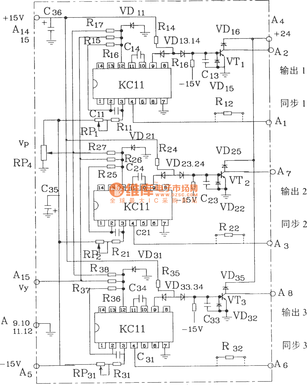
The KCZ3 is an integrated three-pulse triggering component designed for use in three-phase half-bridge inverters. Each phase output pulse can reliably drive a high-power thyristor and is adaptable to various phase voltages. The electrical parameters are as follows: Phase...
%2Bdecoder%2BCircuit%2Bschematic%2Busing%2BM8870.png)
This DTMF (Dual Tone Multi Frequency) decoder circuit identifies the dial tone from the telephone line and decodes the key pressed on the remote telephone. For the detection of DTMF signaling, the IC MT8870DE, a touch tone decoder IC,...
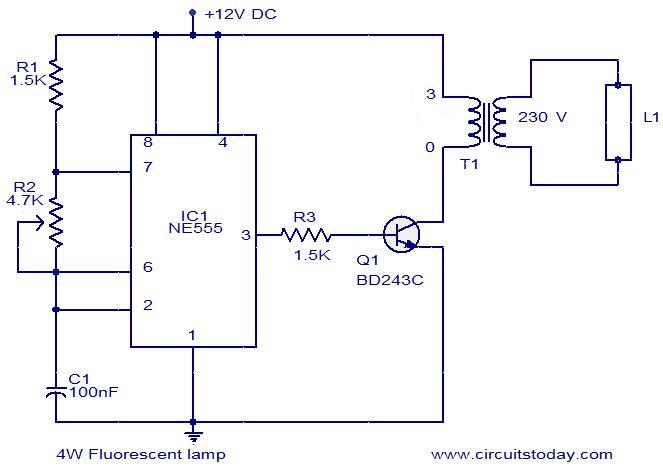
This is a simple 4W fluorescent lamp driver circuit that can be operated from a 12V supply. The first part of the circuit includes a NE555 timer IC configured as an astable multivibrator. The output pulses from the IC...
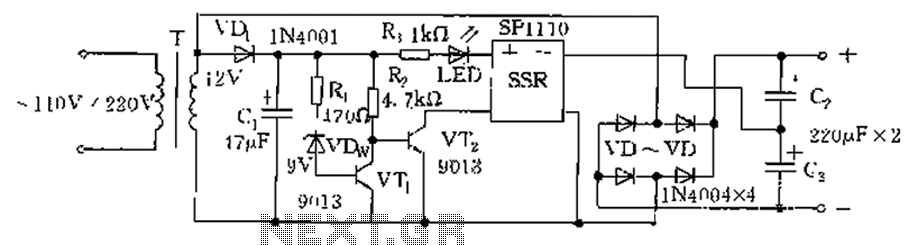
The circuit is automatically converted to a low-voltage configuration. A 220V AC supply is stepped down by transformer T. After this, the breakdown voltage of diode VDw causes transistors VT1 and VT2 to turn off, resulting in the solid-state...
The two unspecified polarized capacitors (one directly above the transformer and one directly to the right of the transformer) are actually each a pair of 470 µF capacitors in parallel (for a total of four 470 µF capacitors). These...