
UV sensor schematic circuit

The UV sensor circuit operates based on the photoelectric effect, where the absorption of UV radiation by the cathode material leads to the emission of electrons. The cathode is typically constructed from a material that has a low work function, allowing it to emit electrons efficiently when exposed to UV light. The quartz glass tube serves as a protective barrier while allowing UV wavelengths to pass through, ensuring that the sensor responds accurately to UV radiation.
In this circuit, the anode collects the emitted photoelectrons, creating a measurable current proportional to the intensity of the UV radiation. The output current can be amplified and processed to provide a readable signal, which may be displayed on a meter or used in a feedback loop for further control applications.
The schematic may include additional components such as resistors to limit current, capacitors for filtering noise, and operational amplifiers for signal conditioning. The design should ensure that the sensor is calibrated for the specific wavelength range of interest, as different materials may respond variably to UV light. Proper shielding and grounding techniques should also be implemented to minimize electromagnetic interference, ensuring the accuracy and reliability of the sensor's output.
Overall, the UV sensor circuit is a critical component in applications ranging from environmental monitoring to industrial safety, where the detection of UV radiation is essential for assessing exposure levels.The figure is a schematic circuit of UV sensor. When UV sensor is coupled by voltage between the cathode and anode, and the UV radiation gets through the quartz glass tube on the cathode of the optical surface, because of the cathode material coated with electron emission, cathode will release photoelectrons.Influenced by the strong electric field, photoel.. 🔗 External reference
Related Circuits
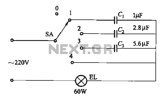
A dimming circuit capacitor circuit is illustrated in Figure 2-63. When the switch SA is moved from position "1" to "3," the capacitance increases in ascending order, resulting in the light bulb brightness also increasing correspondingly. When SA is...
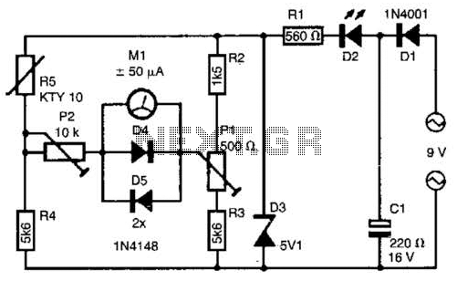
The telephone line tester comprises a meter used to measure line voltage in both the on-hook and off-hook states, three resistors (including one variable resistor), a pushbutton switch, and a modular telephone connector. When the circuit is connected to...
The TCM3105 FSK modem chip from Texas Instruments enables the construction of a modem compatible with Bell 202 or CCITT V23 standards. This modem circuit can transmit data at baud rates of 75, 150, 600, and 1200, and receive...
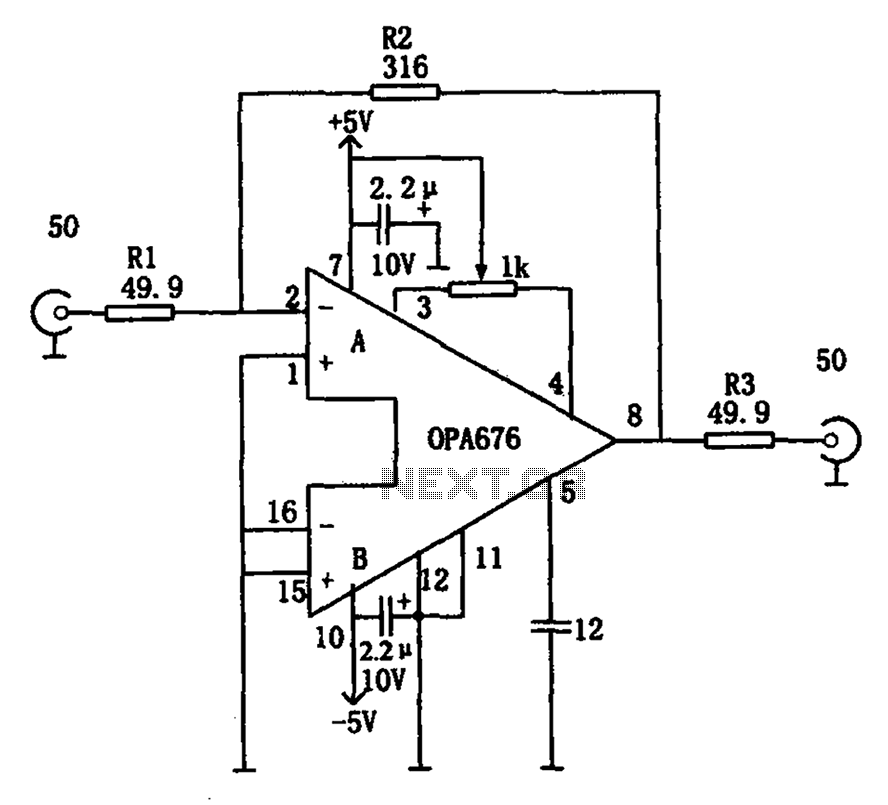
The circuit features a broadband video amplifier with a 50-ohm input/output impedance. To ensure optimal signal transmission and minimize reflected signals, it is often necessary to match the input and output impedances of the amplifier. The broadband video amplifier...
A hoist rated at 22kW and below is equipped with a power-saving Y-conversion circuit, as depicted in the figure. This circuit enhances the standard hoist design by incorporating a CJ20-10A exchange contactor. The implementation of the Y-conversion circuit during...
The Motorola company's MC14440 CMOS integrated circuit is designed for timing and displaying calendar functions. It utilizes a 32.768 kHz NT cutting type quartz crystal along with fine-tune capacitance to generate time-based signals. The display circuit operates on a...