
Bike Guard Alarm Circuit

The described circuit functions as a theft prevention alarm system for motorcycles, leveraging a combination of passive and active components to create a reliable security measure. In its armed state, the system remains dormant, consuming minimal power until activated by unauthorized access. The use of a capacitor (C1) serves as a time delay mechanism, preventing false alarms while allowing legitimate users time to start the bike without triggering the alarm.
The SCR is pivotal in controlling the buzzer's operation, as it allows for a high-power output necessary for audible alarms. The transistor T1 acts as a switch, ensuring that the SCR only conducts when the voltage across C1 reaches a predetermined threshold, indicating that the bike is likely being tampered with. This design minimizes power consumption in the armed state, as the circuit does not draw significant current until the alarm is triggered.
For installation, the circuit should be placed in an inconspicuous location to deter potential thieves from locating the alarm system. The hidden switch S2 must be easily accessible to the bike owner but not easily found by an intruder. The option to replace the buzzer with a more powerful horn provides flexibility in sound output, allowing customization based on user preference for alarm volume.
Adjustability in the time delay through component selection (C1 and R2) allows for fine-tuning the system's sensitivity and response time, accommodating different user needs and scenarios. The circuit's reliance on standard components ensures ease of repair and maintenance, making it an excellent choice for enhancing motorcycle security. The overall design reflects a balance of simplicity, functionality, and effectiveness in providing theft deterrence.This Simple circuit can be used to Guard your bike from theft. It gives a loud alarm tone if somebody tries to start the bike. The alarm disables only when the hide switch S2 is opened. The circuit has little component count and can be easily fixed in the bike. Working of the circuit is simple. The alarm generator buzzer or Horn is activated by an SCR and its triggering is under the control of the transistor T1. In the Armed position, Switch S2 is closed and S1 (Key switch of the bike) is opened. In this state, T1 will not conduct and SCR and Buzzer remains idle in armed position. When somebody turns on the Key switch of the Bike using a duplicate key, Capacitor C1 charges through R1, D1 and R2. It will take a time delay of few minutes to attain full charge in C1. When C1 fully charges T1 conducts and triggers the SCR. Buzzer connected to the Anode of SCR gets electrical path and it sounds the alarm. LED also lights to indicate the theft. The time delay is added through C1 so that the alarm will sound only after the bike is started. This aborts the attempt of theft. The unit should hide in a place like the Carrier Box. So that switch S2 can be protected. An additional bike horn can be connected in the place of the buzzer to get loud sound. Connection point from R1 should go to the key switch point that goes to the engine so that; the unit will be activated only if the key switch is closed.
Time delay can be changed by changing the value of C1 or R2. Hide switch S2 should be kept closed for arming the bike only after removing the switch key. Power to the circuit is obtained from the 6/12 volt bike battery. High current type transistor T1 and SCR are used to handle the high power of bike battery. Use 1 watt resistors to handle high power. 🔗 External reference
Related Circuits
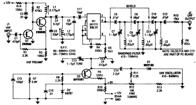
An NE592 or LM733 is utilized as a general-purpose video amplifier in this schematic. J2 and J3 deliver two anti-phase outputs. R2 functions as a gain control. The bandwidth is approximately 100 MHz. The NE592 and LM733 are integrated circuits...

The circuit consists of two balanced components forming a simple Beat Frequency Oscillator (BFO) metal detector. The BFO utilizes a ready-assembled and tested circuit board with a PIC 12F675 chip at its center. This passive detector employs a detector...

This sound wattmeter utilizes a series of colored LEDs as a scale to display the relative power output of an amplifier in watts. It is designed for easy integration into a speaker box, requiring only a connection to a...
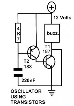
This schematic diagram represents a basic oscillator circuit utilizing two transistors. When the transistors and several passive components are connected as illustrated, the circuit begins to oscillate. The oscillation frequency can be modified by altering the values of either...
The main ΣΔ loop operates in steady state and is fully controlled by summing comparator Q2. This comparator amplifies the ripples of the sensed inductor current and output voltage with gains KI and KV, respectively, to generate an internal...
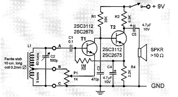
This is a compact and straightforward FM radio receiver capable of tuning into local FM stations. Its minimalistic design renders it suitable for various applications. The FM radio receiver circuit typically consists of several key components that work together to...