
bipolar chopper drive circuit

A bipolar chopper drive is an essential circuit configuration used in stepper motor control systems, particularly for achieving precise current regulation. This method employs a bipolar transistor or MOSFET switching arrangement to modulate the voltage applied to the motor windings, enabling efficient and accurate control of the motor's torque and position.
The bipolar chopper drive operates by rapidly switching the power transistors on and off, creating a series of voltage pulses that are applied to the motor coils. This pulse-width modulation (PWM) technique allows for the adjustment of the effective voltage and current flowing through the motor, which directly influences its performance. The chopper drive circuit typically includes a microcontroller or dedicated driver IC that generates the PWM signal based on the desired motor speed and load conditions.
Key components of the bipolar chopper drive include the power transistors, flyback diodes, current sensing resistors, and control circuitry. The transistors are responsible for switching the current, while the flyback diodes protect the circuit from voltage spikes generated when the inductive motor coils are de-energized. Current sensing resistors provide feedback to the control circuit, allowing for real-time adjustments to maintain the desired current levels.
This method is particularly advantageous for stepper motors because it minimizes power loss and heat generation, enabling higher efficiency and better performance over a range of operating conditions. Additionally, the precise control afforded by the bipolar chopper drive allows for smooth motion and improved torque characteristics, making it suitable for applications requiring high levels of accuracy and responsiveness.In today s blog we re going to examine a bipolar chopper drive, a common method for precision current control in stepper motors.. 🔗 External reference
Related Circuits
This sound effects circuit is designed to function as a signal distorter. When utilized with an electric guitar, it enables the creation of unique sound effects. The sound effects circuit operates by manipulating the input audio signal from the electric...
A bandpass filter allows a specific range of frequencies to pass while rejecting frequencies that fall outside the upper and lower limits of the passband. The frequencies that are permitted to pass are referred to as the passband, which...
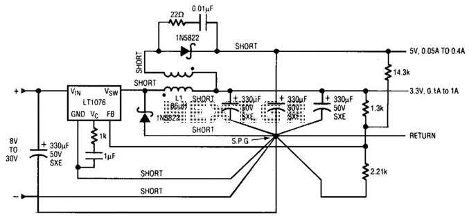
Input voltages can range from 8 V to 30 V. The load range for the 5 V output is from 0.05 A to 5 A, while the load range for the 3.3 V output is from 0.1 A to...
On a mountain bike, a common issue with traditional flashing LED lights from stores is the frequent problem of flat batteries and lights detaching. As an electronics student, a better solution was sought. A front wheel with a built-in...
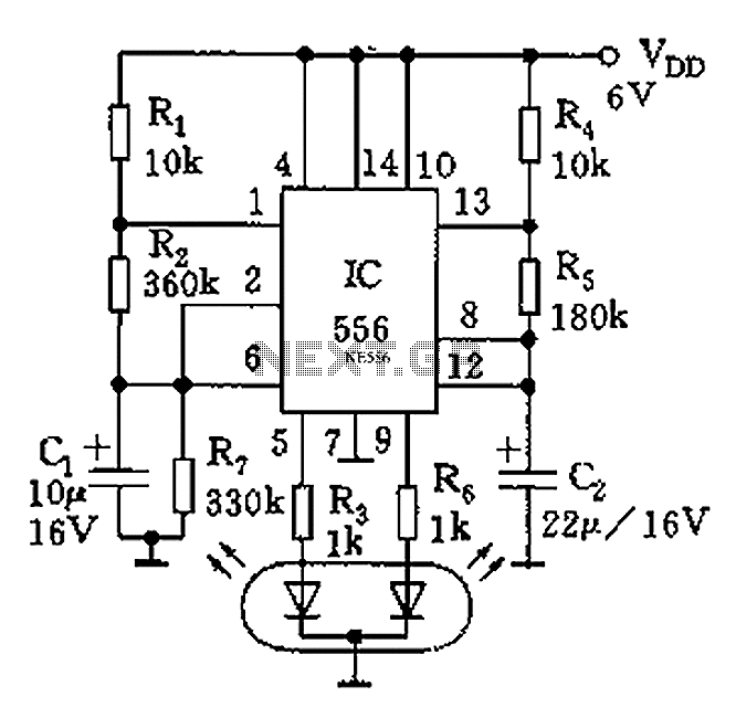
The circuit features a dual-core 556 timer IC and a light-emitting diode (LED) tube. The left half of the IC (556 1/2) comprises resistors R1, R2, capacitor C1, etc., generating a frequency of approximately 2 Hz in a multivibrator...
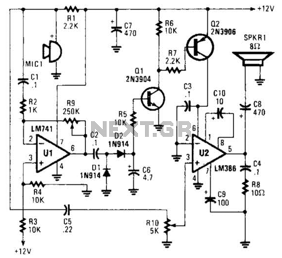
An omnidirectional electret microphone is utilized to capture sound and convert it into an electrical signal. The output from the microphone is directed along two pathways. In the first pathway, the signal is routed to the inverting input at pin...