
Bipolar Stepper Motor Driver Circuit

The circuit utilizes a 4017 decade counter to sequentially activate transistor switches that control the windings of a 12-V stepper motor (MOT1). The low-frequency oscillator, comprising operational amplifiers U1-a and U1-b, generates the clock signals necessary for the counter's operation. The output of the 4017 activates the transistors in a specific sequence, allowing for precise control of the motor's movement.
Resistors R9 and R10 are critical components selected to match the current requirements of the stepper motor. These resistors ensure that the transistors operate within their safe limits, preventing overheating or damage due to excessive current. The choice of these resistors is based on the motor's specifications, particularly its rated current.
The frequency of the oscillator directly influences the speed of the stepper motor. For instance, a 3.3-Hz clock signal results in a motor speed of 1 rpm, while increasing the frequency to 33 Hz allows the motor to operate at 10 rpm. This relationship between frequency and motor speed can be utilized to achieve various operational speeds by adjusting the oscillator's frequency output. The design provides flexibility in controlling the motor's speed, making it suitable for applications requiring precise movement and positioning.
Overall, this circuit design effectively integrates a decade counter, low-frequency oscillator, and transistor switches to control a stepper motor, demonstrating a practical approach to motor control in electronic applications. A 4017 decade counter/divider driven from a low-frequency oscillator (Ul-a and Ul-b) is used to drive transistor switches to sequence the windings, as is needed. MOT1 is a 12-V stepper motor. R9 and RIO are selected for the motor`s current rating. A 3.3-Hz signal from Ul will cause the motor to run at 1 rpm, a 33-Hz signal will result in 10 rpm, etc.
Related Circuits
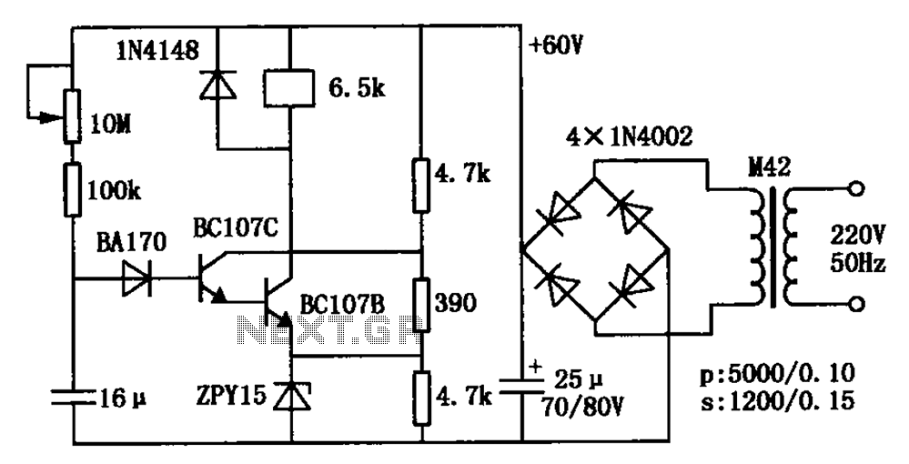
The circuit is a relay delay pull transistor configuration. Initially, when powered, the 16 µF capacitor has a voltage of zero, resulting in both transistors being off, and the relay remains inactive. As the 16 µF capacitor charges over...
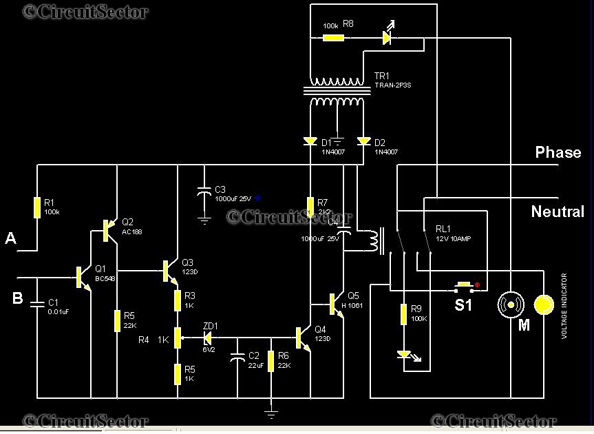
This is an automatic water tank controller designed to manage the operation of a water pump using a 12V 10A relay. When the water level in the tank creates a short circuit between points A and B in the...
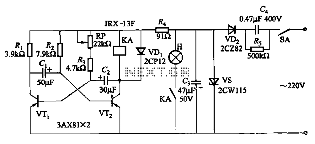
The circuit features a self-excited multivibrator composed of transistors VTi and VTZ. It includes an adjustment potentiometer RP and two RC networks that influence the transistors' parameters, specifically the timing for light activation and deactivation. The described multivibrator circuit utilizes...
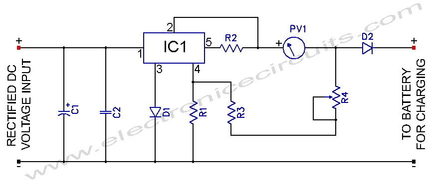
L200 12V Constant Voltage Battery Charger Circuit. This battery charger is based on the L200 regulator IC. The L200 is a five-pin adjustable voltage regulator. The L200 constant voltage battery charger circuit is designed to provide a stable 12V output...
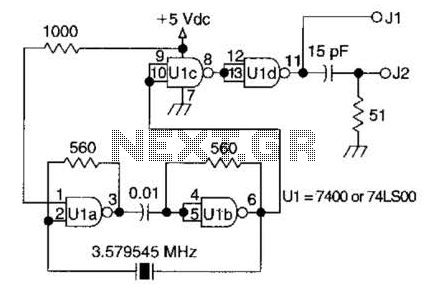
A circuit utilizing one 7400 TTL can operate with fundamental type crystals ranging from 1 to approximately 13 MHz. The output is rich in harmonics, making this oscillator suitable for calibration and testing applications. The circuit in question employs a...

This circuit is designed for an LM1893 power line modem, which facilitates information transfer between remote locations using the power mains. The LM1893 serves as a power line interface for half-duplex (bi-directional) communication of serial bit streams employing various...