
lm1893 power line modem circuit

The LM1893 power line modem circuit operates by utilizing the existing electrical wiring to transmit and receive data, effectively turning the power lines into a communication medium. The half-duplex nature of the communication allows for data to be sent and received, albeit not simultaneously, which is suitable for many applications where full-duplex communication is not critical.
The design includes essential elements such as an impulse noise filter that mitigates interference from electrical noise present on the power lines, ensuring clearer signal reception. The integrated phase-locked loop (PLL) demodulator enhances signal integrity by locking onto the carrier frequency, thus enabling precise extraction of the modulated data signal.
For the transmission side, the circuit applies a sinusoidal carrier wave that provides the necessary frequency for FSK modulation. This modulation technique allows the encoding of digital information onto the carrier wave by varying its frequency, which is particularly effective in noisy environments typical of power line communications. The rugged on-chip driver ensures that the signal can be transmitted over long distances without significant degradation.
The inclusion of a COPS controller allows for additional processing capabilities, enabling the system to handle various control tasks and improve overall functionality. The discrete components in the circuit complement the LM1893 and COPS controller, providing necessary support for filtering, amplification, and signal conditioning.
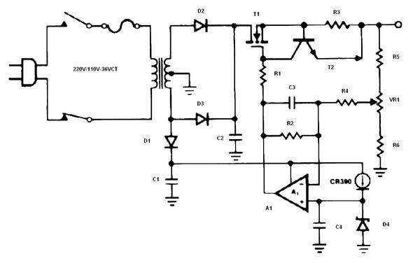
Overall, this circuit exemplifies a robust solution for power line communication, leveraging existing infrastructure to facilitate data transfer, making it a versatile choice for remote communication applications.This is a circuit for an LM1893 power line modem circuit. This circuit is used to transfer information between remote location by using the power mains. This circuit uses LM1893 that is used as a power line interface for half-duplex (bi-directional) communication of serial bit stream of virtually any coding. This is the figure of the circuit; To g ive maximum range, impulse noise filter and a PLL-based demodulator are combined in reception. In transmission, a sinusoidal carrier is impressed and FSK modulated on most any power line via rugged on-chip driver. Besides LM1893, this circuit also uses a COPS controller and discrete components. [Circuit schematic source: National Semiconductor Notes] 🔗 External reference
Related Circuits
Input J4 features an offset function that is activated only when no plug is inserted into J4, as the switching contact of J4 connects to the positive supply voltage through the protection resistor R8. The inverting sum of all...
The schematic diagram originates from a circuit designed as a battery charger/power supply with an output of 14V and a maximum current of 4A, utilizing the VN64GA MOSFET. This high-performance battery charger is specifically engineered for gelled electrolyte lead-acid...

An RF power amplifier is an electronic amplifier used to convert a low-power radio-frequency signal into a larger signal of significant power, typically for driving the antenna of a transmitter. It is optimized for high efficiency, high output power...
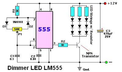
The LM555 timer IC can be utilized in various electronic projects, including the creation of an analog timer. According to the datasheet, the LM555 is versatile and can be adjusted to set timers based on specific requirements. The schematic...
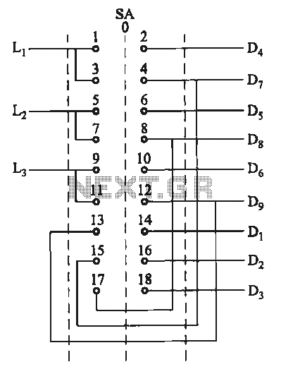
The motor switch control circuit depicted in the figure provides two speed settings for counter-steering, allowing for operation at two speeds in opposite directions. The motor switch control circuit is designed to facilitate the operation of a motor at two...
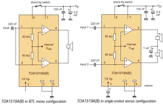
The audio amplifier circuit is based on the TDA1519 amplifier IC, which is designed for audio applications. The TDA1519 has a power output range of 2 to 6 watts. This amplifier is a Class B dual-output type and comes...