
Seven blinker circuits

The described multivibrator circuit utilizes two transistors (VTi and VTZ) configured to create an astable multivibrator, which generates a continuous square wave output. This configuration is commonly employed in applications such as flashing lights or tone generation. The operation of the circuit hinges on the charging and discharging cycles of the capacitors within the RC networks, which dictate the frequency of oscillation.
The adjustment potentiometer RP plays a crucial role in fine-tuning the timing characteristics of the circuit. By varying its resistance, the time intervals for which the lights are turned on (high state) and off (low state) can be adjusted. This allows for customization of the light blinking rate, enhancing the versatility of the multivibrator in different applications.
The RC networks connected to each transistor help establish the necessary time constants for the oscillation. The resistors and capacitors can be selected based on the desired frequency range, with the time period of the output signal being determined by the formula T = 0.693 * (R1 + R2) * C, where R1 and R2 are the resistances in the RC networks and C is the capacitance. The output from the multivibrator can be connected to various load devices, such as LEDs or other light sources, to create visual indicators or alerts.
Overall, this self-excited multivibrator circuit exemplifies a straightforward yet effective design for generating timed signals, suitable for a variety of electronic applications. By the transistor VTi, VTZ composition self-excited multivibrator. Adjustment potentiometer RP and two RC transistors related parameters, time to change the lights and the ligh ts out time.
Related Circuits
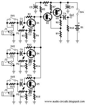
The following circuit illustrates a Mini Audio Mixer with Level Control Circuits. Features include switchable high/low sensitivity, providing high performance. The Mini Audio Mixer circuit is designed to facilitate the mixing of multiple audio signals while allowing for level control...

The circuit described is straightforward yet efficient in its operation. The transistor Tr1 is utilized in a grounded base mode, with an input directed to its emitter to facilitate a low impedance input. The circuit is designed to operate effectively...

A multimeter cannot be used to test a crystal oscillator. Instead, a dedicated circuit is required, capable of checking crystals within the frequency range of 100 kHz to 900 MHz. This circuit is easy to construct and cost-effective. To construct...

The telephone repeater is a circuit designed to amplify the call signal, making it louder than the original. This circuit has been developed in response to specific requests. The telephone repeater circuit functions by receiving the incoming audio signal from...

The 555 Astable generates a clock for this circuit, functioning as an oscillator that produces a square wave output at pin 3. This output is counted by the CD4017 decade counter, which creates a running lights effect. The CD4017...

The circuits in Figure 1 and Figure 2 demonstrate specific advantages over the circuit presented in the Design Idea in EDN, titled "Circuit detects first event," published on May 3, 2001, page 89. The n-player first-event detection circuit provides...