
Birds singing analog signal generator circuit

The described circuit serves as a versatile analog signal generator, capable of producing low-frequency chirp sounds reminiscent of birds. It incorporates multiple CD4069 inverters, which are utilized to create oscillators that generate the necessary frequencies for both the low-frequency and audio signals. The use of ultra-low frequency oscillators allows for the generation of signals that can produce very slow oscillations, which are essential for mimicking the natural rhythm of bird songs.
The clock signal produced by the low-frequency oscillators is fed into the counting device IC2, which counts the pulses and determines the output based on its configuration. This output is essential for controlling the pole tube matrix, which shapes the audio output further. The design allows for flexibility in configuring the output signals through the various Q outputs, which can be adjusted to create different chirp patterns.
The audio oscillator, formed by inverters 3 and 4, works in conjunction with the low-frequency oscillator to modulate the audio output. The modulation is achieved by varying the amplitude or frequency of the audio signal based on the low-frequency oscillation, resulting in a dynamic sound output that can change over time, mimicking the natural variability of bird calls.
The inclusion of analog switches ES1 to ES4 adds a layer of control to the circuit, allowing for selective activation of certain components within the circuit. This feature enhances the circuit's functionality, enabling the user to tailor the sound output by engaging or disengaging specific diodes (VD2 to VD9) and resistors (R1 and R11). This modular approach allows for experimentation and customization of the chirping sounds produced, making it suitable for various applications in sound synthesis and educational projects. Birds singing analog signal generator circuit Shown is an analog chirp signal generator circuit. The inverter circuit consists of six CD4069 composed of three oscillators, two inverters lcl l, 2 ultra-low frequency oscillator composition, the oscillation frequency is a fraction of hertz, the signal as a clock signal into the counting device IC2 of the CLK terminal, depending on the number of input pulse, Q1-Q9 in different configuration output of IC2 to control subsequent fftj- pole tube matrix. ICI inverters 3,4 composed audio oscillator for generating an audio signal. IC1 non-inverter S, 6 composed of low-frequency oscillator. Audio oscillator control signal output by the low-frequency oscillator, so the audio output of the oscillator is modulated by an audio signal.
Low frequency oscillation signal output by C4, by B-RII to one or more of the audio oscillator, 8 ~ Rl1 whether the access depends on the analog switch ES1 ~ ES4 on and off, but also by ES1-ES4 control in VD2-VD9.
Related Circuits
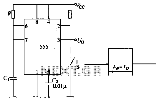
Introduction to the circuit schematic depicted in Figure 3-3. In this configuration, the 555 timer is utilized in a monostable mode, typically activated by a normally open push button switch. The circuit operates in an S-shaped state, where the...
This innovative buzzer circuit incorporates a relay connected in series with a small audio transformer and a speaker. When the switch is activated, the relay is energized through the primary winding of the transformer and the closed relay contact....

This is an economical FM booster circuit designed to enhance the reception of distant FM stations on local radios. The circuit diagram features a common-emitter tuned RF preamplifier utilizing the VHF/UHF transistor 2SC2570. The circuit's output should be directly...

A circuit breaker is an automatically operated electrical switch designed to protect an electrical circuit from damage caused by overload or short circuit. Its basic function is to detect a fault condition and, by interrupting continuity, immediately discontinue electrical...
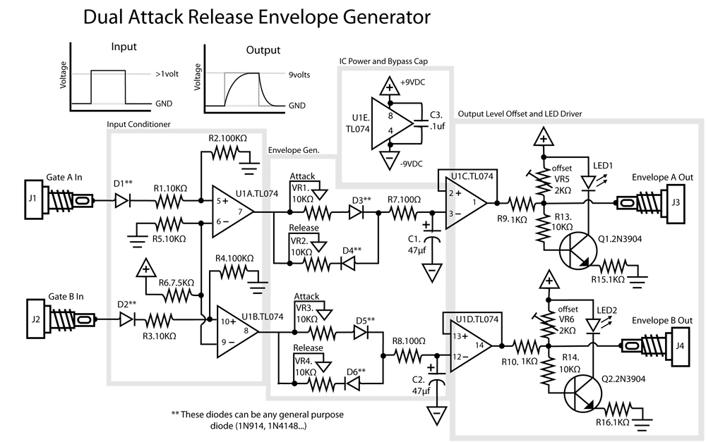
This is a dual Attack/Release envelope generator that has been added to the Modular Benjolin design. While not essential, it provides enjoyable functionality, particularly when used alongside the modular rungle bit output mod. The circuit is straightforward, making it...
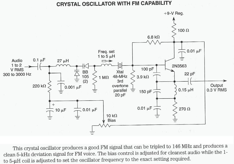
The 7th overtone of 18 MHz (17m) is 144 MHz (2m) directly within the CW region. Icarus is a high-altitude balloon (HAB) project funded by advertising revenue, which has successfully launched numerous balloons that captured impressive photographs. Robert Harrison...