
Black Light

The described circuit utilizes a 6-volt power source, which can be either a battery or a power supply capable of delivering a current of 1 amp or more. The primary component responsible for generating ultraviolet (UV) light is typically a UV LED or a UV lamp.
In a basic configuration, the circuit may include a resistor in series with the UV light source to limit the current and prevent damage to the LED or lamp. The value of the resistor can be calculated using Ohm’s law, taking into account the forward voltage drop of the UV LED or lamp and the desired operating current.
For instance, if a UV LED has a forward voltage of 3.2 volts and a desired current of 20 mA, the required resistor value can be determined as follows:
1. Calculate the voltage drop across the resistor:
Voltage drop = Source voltage - Forward voltage = 6V - 3.2V = 2.8V.
2. Use Ohm's law (V = IR) to find the resistance:
R = Voltage drop / Desired current = 2.8V / 0.02A = 140 ohms.
In practice, a standard resistor value of 150 ohms could be used, which would slightly reduce the current but still allow the LED to operate efficiently.
The circuit may also include a switch to control the operation of the UV light, and possibly a fuse for safety, ensuring that the circuit is protected against overcurrent conditions. Additionally, a heat sink may be necessary if a higher power UV lamp is used, to dissipate heat and maintain optimal operating conditions.
Overall, this simple ultraviolet light circuit can be applied in various applications, including sterilization, curing of UV-sensitive materials, or as a light source for specific scientific experiments. Proper safety measures should be considered when working with ultraviolet light, as it can be harmful to skin and eyes.This circuit is a simple ultraviolate light that can be powered by a 6 volt battery or power supply (such as the power supply on the "Circuits" page) that is capable of supplying 1 or more amps. 🔗 External reference
Related Circuits
This light sensor switch circuit enables the automatic activation of a lamp when ambient light levels decrease, such as during nightfall. The duration for which the lamp remains on can be adjusted using potentiometer P1, with a range of...
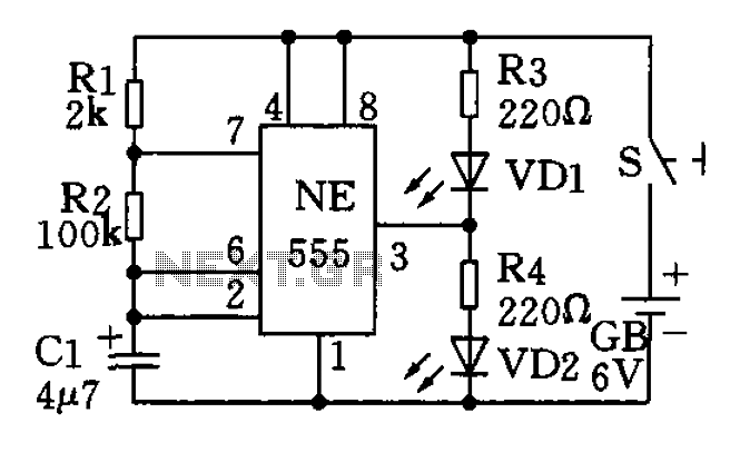
The circuit utilizes a 555 timer as the central component of a flashing light circuit. In normal operation, the light-emitting diodes (LEDs) VD1 and VD2 alternate flashing. The circuit comprises the NE555 timer, resistors R1 and R2, and capacitor...
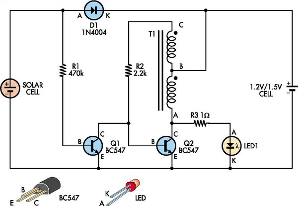
This white LED driver circuit is suitable for garden lighting applications. It automatically activates the LED at night and operates from a single 1.2V NiCad cell, which is recharged by a solar cell during the day. The prototype utilized...
This solar birdhouse light features an economical circuit for a mini solar lighting system. The core component of the circuit is a mini 6V/2W solar panel, which is utilized to charge a 4V/800mAh rechargeable battery. The charging process is...
A solar-powered garden light has been purchased, featuring a solar panel that charges batteries. When darkness falls, three LEDs illuminate until either light returns or the batteries deplete. The control box contains three Ni-MH AA batteries with a capacity...
This circuit operates six LEDs in a "Knightrider scanner mode." The power consumption is primarily influenced by the type of LEDs utilized, especially when employing a 7555 (CMOS version of the 555 timer). Caution is advised when working with...