
Light sensor switch circuit

The light sensor switch circuit typically employs a light-dependent resistor (LDR) to detect ambient light levels. When the light intensity falls below a predetermined threshold, the LDR's resistance increases, triggering a transistor or relay to close the circuit and turn on the lamp.
The circuit consists of several key components: the LDR, a potentiometer (P1) for time adjustment, a timing capacitor, and a resistor to set the timing interval. The timing capacitor, in conjunction with the resistor, determines how long the lamp stays illuminated after the LDR detects low light levels.
When designing the circuit, it is essential to select an appropriate transistor or relay that can handle the lamp's load. The output stage is typically connected to the lamp via a relay to ensure safe operation, especially if the lamp operates at mains voltage.
To enhance the functionality of the circuit, a diode can be included across the relay coil to protect against back EMF when the relay is switched off. Additionally, an LED indicator may be added to show when the circuit is active, providing a visual confirmation of operation.
Overall, this light sensor switch circuit is a practical solution for automating lighting in response to changing ambient light conditions, making it suitable for outdoor lighting, garden lights, or any application where automatic light control is desired.This light sensor switch circuit allows the automatic connection of a lamp when the light is low (at nightfall) and will maintain the lamp ON for a certain period of time. This time can be adjusted with P1 between 1 and 5 hours. The switch.. 🔗 External reference
Related Circuits
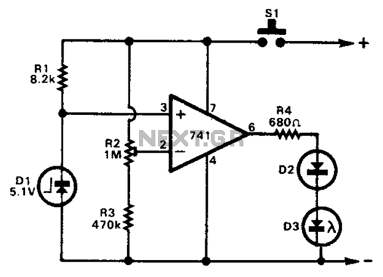
The 741 operational amplifier can function as a voltage comparator. It features a non-inverting input and a Zener-controlled voltage source, with a reference voltage set at 5.1V. Resistor R2 is used to adjust the in-phase input voltage to half...
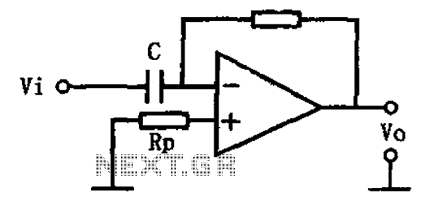
This circuit illustrates a basic differentiating circuit. The differential operation circuit can process input and output signals, establishing a relationship between the output and the input. A basic differentiating circuit is designed to produce an output that is proportional to...

This page presents information on infrared - Across The Track train detection circuits. The circuits are designed around the LM339 comparator chip and can use a wide assortment of matched infrared - emitter / detector pairs. The infrared "Across The...
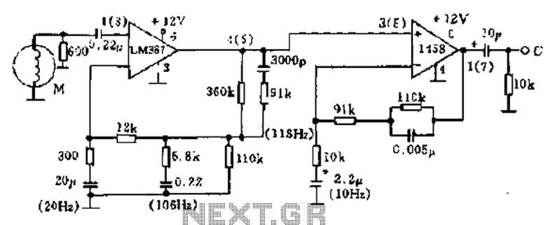
The phonograph pickup head is represented in the schematic as component M, which generates the pick-up signal and is processed through an LM387 amplifier circuit. The LM387 is part of the LM38X series, recognized for its advanced linear amplifier...
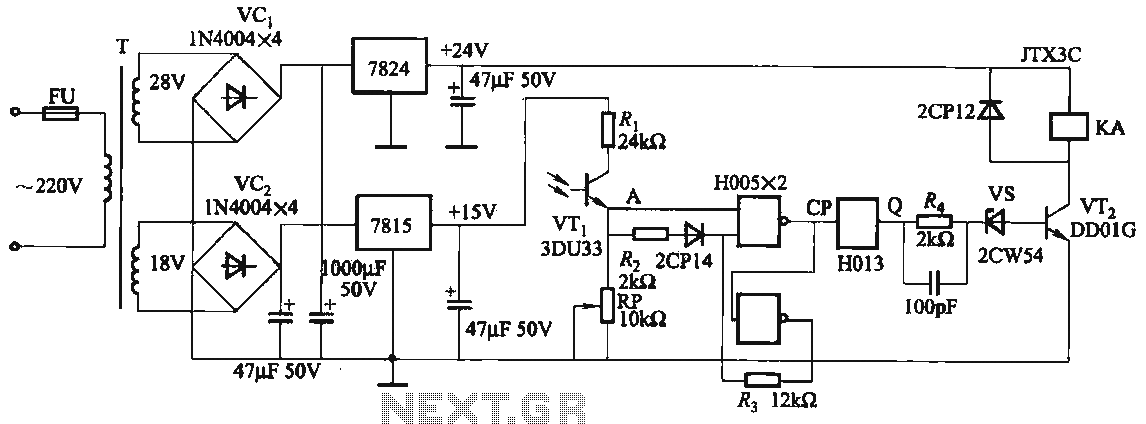
The circuit features a robust anti-jamming capability, making it suitable for demanding applications. It includes a phototransistor (VTi), a Schmitt trigger (H005), a JK flip-flop (H013), a power amplifier circuit, a relay (KA), and various actuators and other components....
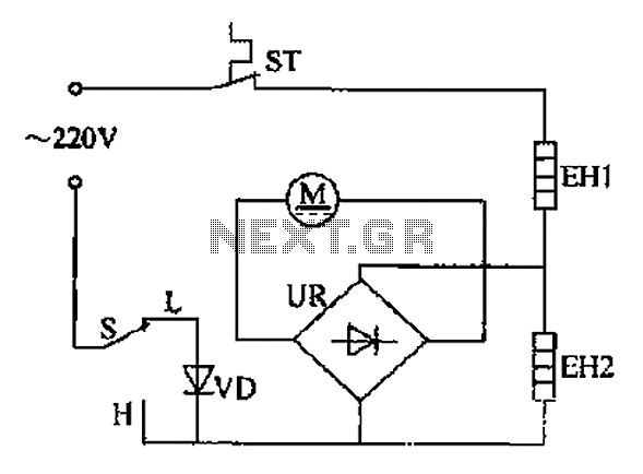
The comb electric circuit illustrated in Figure 1-3 features two temperature settings. By toggling switch S to either the L or H position, different temperatures can be achieved. Once switch S is activated, the circuit powers the heating wires...