
Blinken lights circuit
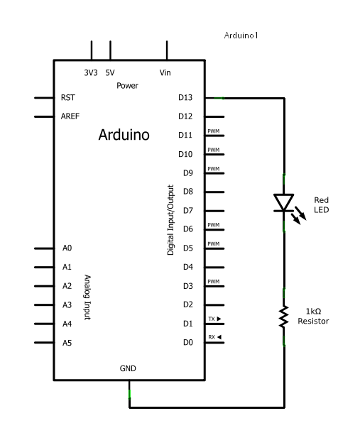
In the context of an Arduino-based LED blinking circuit, the schematic typically includes the following components: an Arduino board, a red LED, a 1000 ohm resistor, and a breadboard for temporary assembly. The LED should be connected in series with the resistor to limit the current flowing through the LED, preventing it from burning out. The anode (longer lead) of the LED connects to one end of the resistor, while the other end of the resistor connects to the +5V pin on the Arduino. The cathode (shorter lead) of the LED is connected to one of the ground pins on the Arduino. This setup ensures that when the Arduino sends a HIGH signal to the LED pin, the current will flow through the LED and the resistor, illuminating the LED.
The code for making the LED blink can be written in the Arduino IDE, utilizing functions such as `pinMode()` to set the LED pin as an output and `digitalWrite()` to turn the LED on and off. The use of `delay()` allows for control of the timing between the LED's on and off states. By adjusting the delay values, the blinking speed of the LED can be modified, demonstrating the flexibility of programming in conjunction with hardware components. This simple circuit serves as an introductory project for understanding the interaction between hardware and software in electronics, highlighting the importance of component selection and circuit design principles.As mentioned earlier, Arduino consists of two major parts: the hardware (the Arduino board) and the Software (the IDE). The advantage of using the Arduino is that we can build a circuit and then modify how it responds by changing the code (instead of changing the hardware).
The focus of this lesson will be on building a basic circuit with an LED. We will then examine the code that makes the LED blink. So you don`t have to solder things together, you will temporarily build your circuits on the breadboard provided with your kit and change the code to modify how the device responds. This circuit calls for two pieces of hardware in addition to the Arduino, a red LED and a 1000 © resistor.
LEDs are the lights in your kit, and a red one should be easy to find, so take one out now. The resistor might be a bit trickier because resistors are labeled with stripes instead of numbers. So let`s learn a bit about resistors so we know why they are used, and can pick the right one for the diagram. Resistors reduce the flow of electricity, or current, in a circuit. All electrical components resist to some degree, even wires, but resistors are designed specifically for that purpose.
When you complete a circuit that has no resistance, current will flow through it as fast as the power source can provide it. If you have a source with a lot of available power this results in heat which may burn you or melt and ruin electrical components.
A common metaphor for electrical current is water in pipes. If you have a pipe that is open to air, this is a bit like a circuit that is connected to ground. If you have a high pressure source and a wide pipe then a lot of water will flow through the pipe to air. If there is a narrow spot in the pipe somewhere this will slow the water and less water will flow out of the pipe where it opens to air.
Sometimes you want a lot of water to flow to air, as in a fire hose. Sometimes you want a little water to flow to air, as in a water fountain. The same goes for electricity. Sometimes you want a lot of current because you are driving a motor. Other times you want only a little because you are driving a small LED. If your Arduino is plugged into a USB port two of these values are known - you usually use the 5V power pin, and USB can supply a maximum of 500mA or 0. 5 Amps. Using Ohm`s law I can calculate that an Arduino circuit between the +5V pin and any of the ground pins must have a minimum total resistance of 10 Ohms and be the only thing drawing current to be safe.
If your Arduino draws more than 500mA of current through USB, it will shut down to protect your computer. The computer itself may also shut down the USB port to protect itself. If this happens, try pressing the reset button on the Arduino. If that doesn`t work you may have to unplug the USB cable from the computer. Never try connecting +5V directly to ground when using the DC power plug. The last point is kind of complicated, but lots of interesting circuits make use of this voltage adjustment property.
In the LED circuit, the resistor is protecting the LED. Resistance to current is measured in ohms. Ohms are represented with the greek symbol Omega ( ©). You saw this symbol in the circuit schematic above. When a circuit diagram calls for a resistor with a certain resistance it is important to get the right one. Resistors come in a very wide range of values. They are also typically very small. So rather than trying to print a resistor`s value directly on its case, a color coding system is used.
This same color system is sometimes used for capacitors too, so it`s a good idea to learn it. The system goes like this: The first three bands express ohms in scientific notation. The number represented by the first two bands is multiplied by 10 to the power of the number on the third band. Another way of thinking of this is the number represented by the third band represents how many zeros follow the numb
🔗 External reference
Related Circuits
The goal is to utilize a PC to measure the outdoor temperature using a serial-connected device equipped with a probe that can be conveniently placed outside. Although various options were found through online searches, many appear to be overly...

Transistors are essential components of electronic circuits. The success of a circuit design depends on the selection of the appropriate transistor type and the calculations involved. Transistors serve as fundamental building blocks in electronic circuits, playing critical roles in amplification,...

LMD18245 bipolar stepper motor driver circuit design using few electronic parts The LMD18245 is a versatile bipolar stepper motor driver designed to control stepper motors with precision and efficiency. This circuit utilizes a minimal number of electronic components, making it...
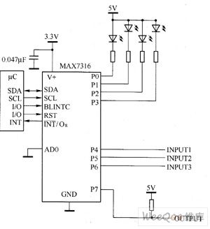
The main technical characteristics of the MAX7316 include a 400 kbps, 2-wire serial interface with a voltage tolerance of 5.5V. The operating voltage ranges from 2V to 3.6V. It features 8-bit PWM control for white LED brightness, with global...
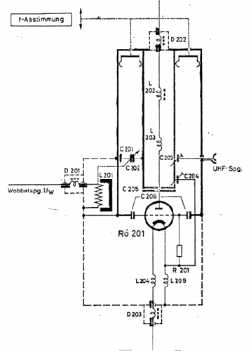
The use of a quarter-wave parallel-wire line as a tuning unit has been discussed in the chapter on Short Lines, where it was pointed out that these circuits have comparatively high Q even at higher frequencies. Their great length...
This circuit is designed for use with inductive pick-up elements and dynamic microphones. Most soundcards feature a line input and a separate input for electret (condenser) microphones. To connect an inductive tape recorder head or a dynamic microphone, an...