
LMD18245 bipolar stepper motor driver circuit design

The LMD18245 is a versatile bipolar stepper motor driver designed to control stepper motors with precision and efficiency. This circuit utilizes a minimal number of electronic components, making it suitable for applications where space and cost are critical factors. The LMD18245 integrates power and control functionalities, enabling seamless operation of stepper motors in various configurations.
The circuit typically includes the LMD18245 driver IC, which can handle a wide range of input voltages and provides high current output, accommodating different stepper motor specifications. Additional components often involved in the design are resistors, capacitors, and diodes, which help in managing the input signals, filtering noise, and protecting the circuit from voltage spikes.
The design can be configured for both full-step and half-step driving modes, allowing for flexibility in motor control. Full-step mode provides maximum torque, while half-step mode offers smoother motion and increased resolution. The circuit can be controlled via a microcontroller or a dedicated stepper motor controller, which sends pulses to the LMD18245 to dictate the stepping sequence.
To ensure reliable operation, the circuit may incorporate thermal management features, such as heat sinks or temperature sensors, to monitor the temperature of the driver IC. Proper heat dissipation is critical to maintain performance and prevent thermal shutdown.
Overall, the LMD18245 bipolar stepper motor driver circuit design is an efficient solution for driving stepper motors in various applications, including robotics, CNC machines, and automation systems. Its simplicity and effectiveness make it a popular choice among engineers and hobbyists alike.LMD18245 bipolar stepper motor driver circuit design using few electronic parts 🔗 External reference
Related Circuits
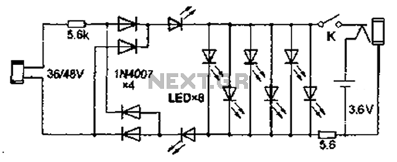
Also known as the Free lamp (commonly referred to as the Myanmar lamp by online sellers), this device operates using the voltage from a standard household fixed telephone line, eliminating the need for batteries or AC power. The lamp...
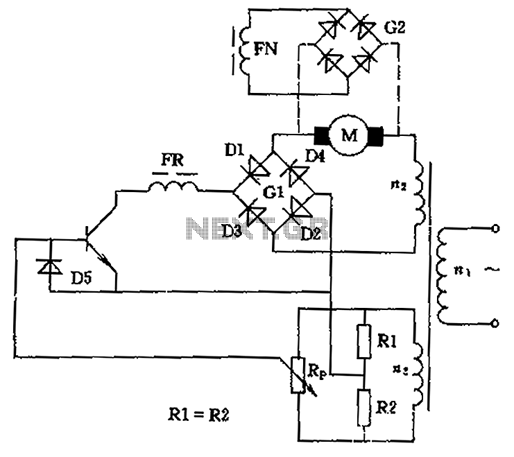
The circuit is designed to control the speed and direction of low-power DC motors, including series and shunt motors. It utilizes a rectifier bridge (G1) connected in series with the motor and linked to the secondary winding (n2) of...
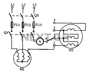
Drying the motor winding circuit current imbalance. Below is a circuit diagram of the motor winding current imbalance drying. The circuit for drying motor winding current imbalance is designed to address the issue of uneven current distribution across the windings...
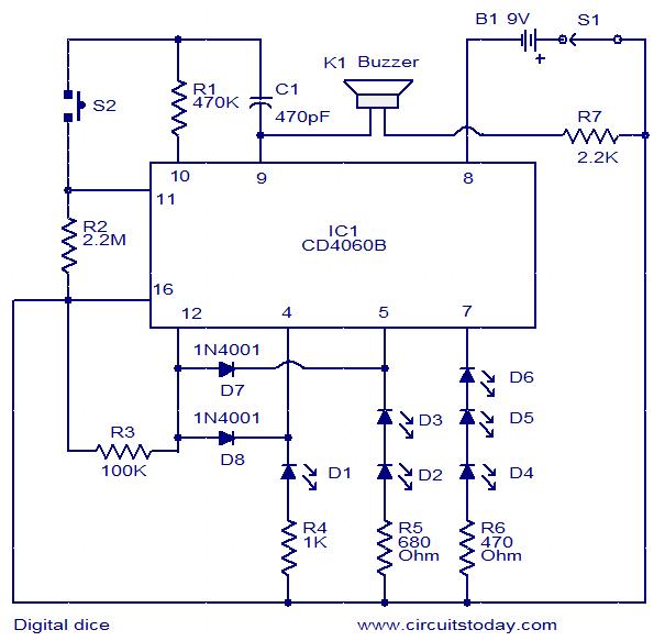
This is a simple and easy-to-construct digital dice circuit. The circuit is based on a single IC, CD4060B. The dice consists of six LEDs marked D1 to D6. The number of LEDs glowing indicates the numeral. The heart of...
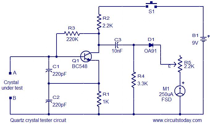
This is a straightforward and cost-effective circuit designed for testing quartz crystals. A Colpitts oscillator is employed using transistor T1. When the crystal is connected between terminals A and B, the circuit generates high-frequency oscillations. These oscillations will only...
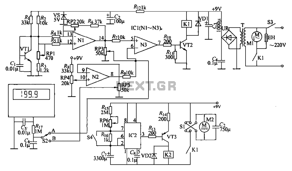
The circuit is illustrated. It includes a DC power circuit with a power switch (S3) that converts 220V AC voltage through a buck converter (T), a rectifier (UR), and filter capacitors (C3 and C4) to generate a +9V output....