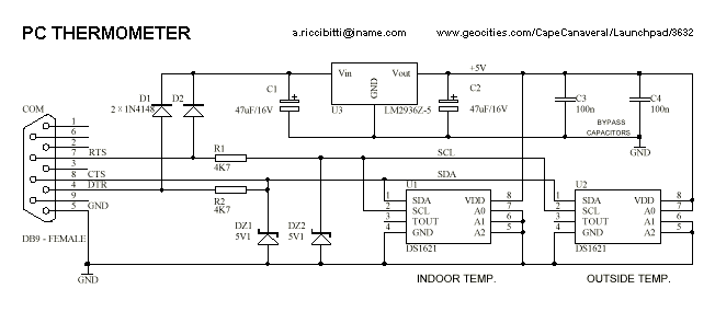
PC RS232 thermometer circuit

The goal is to utilize a PC to measure the outdoor temperature using a serial-connected device equipped with a probe that can be conveniently placed outside. Although various options were found through online searches, many appear to be overly complex and priced around $100.
To achieve the desired functionality of measuring outdoor temperature via a PC, a simple and cost-effective circuit can be designed. This circuit typically consists of a temperature sensor, such as the LM35 or DS18B20, which provides an analog or digital output corresponding to the temperature. The sensor is connected to a microcontroller, such as an Arduino or Raspberry Pi, which serves as the interface between the sensor and the PC.
The temperature sensor is placed in an outdoor probe, ensuring it is protected from environmental factors while maintaining accurate readings. The microcontroller reads the temperature data from the sensor and converts it into a format suitable for transmission. For a serial connection, the microcontroller can utilize its UART (Universal Asynchronous Receiver-Transmitter) capabilities to send the temperature data to the PC.
The PC can then receive this data through a serial communication interface, such as a USB-to-serial converter, enabling real-time temperature monitoring. Software running on the PC, which can be developed in various programming environments such as Python or C++, will interpret the incoming data, providing a user-friendly display of the temperature readings.
This circuit design is not only straightforward but also offers flexibility in terms of sensor choice and communication protocols, allowing for customization based on specific requirements. By utilizing readily available components, this system can be constructed at a significantly lower cost than commercially available solutions, while still providing reliable performance.We’d like to be able to use a PC to measure the temperature outside. Ideally this would be a serial connected device with a probe that could easily be placed outside. Google found us some, but there seem to be very complex and cost around $100! 🔗 External reference


