
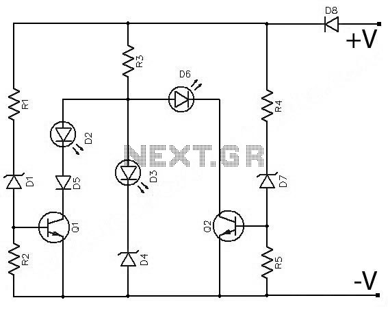
Blinker Indicator

The circuit operates by utilizing two integrated circuit counters, which are pivotal in creating the sequential light pattern characteristic of turn signals. Each counter is responsible for a specific direction of the light display, ensuring that when one side is activated, the corresponding counter begins counting from zero. The reset mechanism is crucial for maintaining the display's functionality. Capacitors C4 and C7 not only serve as timing elements but also ensure that the counters are synchronized with the activation of the blinker lamp.
The NAND gate IC1 plays a vital role in managing the reset pulses for the counters. By generating a reset signal when the blinker lamp is turned off, the circuit is able to initiate a new counting cycle, allowing the display to function continuously without user intervention. The ability to adjust the progression speed of the display through potentiometer P1 provides flexibility in the circuit's operation, accommodating different preferences for visual effects.
The design also incorporates a method for brightness control through resistor R12. This feature is particularly important in automotive applications, where visibility can be affected by ambient lighting conditions. By allowing only one LED to be illuminated at a time, the circuit ensures that the brightness remains consistent and can be easily modified based on user requirements.
Furthermore, the option to replace standard diodes with LEDs enhances the circuit's versatility and modernizes the light display. This modification not only improves energy efficiency but also allows for a broader range of colors and brightness levels, making the blinker indicator more visually appealing. Overall, this circuit exemplifies innovative design principles in automotive lighting, combining functionality with aesthetic considerations.This circuit represents a somewhat unusual blinker indicator for use in a car or model. The running-light display progresses toward the left or the right depending on which directional signal is activated. That`s pretty cool if you`re fond of light-show effects. The circuit consists of two counters (IC2 and IC3), which are reset to zero via C4 or C7 respectively whenever a blinker lamp (La) illuminates. The running-light display thus runs through once and then stops, since the highest counter output is connected to the Enable input. When the lamp goes out, a new reset pulse is issued to the relevant counter by NAND gate IC1. A or IC1. B respectively, and the counter counts all the way up again. The progression rate of the display can be adjusted to the right speed using P1. Only one LED is on at a time (except for the hazard blinker). This allows the brightness to be easily adjusted using R12. Incidentally, the circuit can also be modified by replacing the normal diodes with LEDs, with all of the cathodes connected to ground via R12.
🔗 External reference
Related Circuits
Often, outdoor audio or video recordings suffer from poor quality when the battery is low. If the battery voltage drops below 9V for a 12V recorder, the playback output will be compromised due to variations in the power supply. To...
The above circuit is a precision voltage source and contains a temperature sensor with a negative temperature coefficient. Meaning, whenever the surrounding or battery temperature increases, the voltage will automatically decrease. The temperature coefficient for this circuit is -8mV...
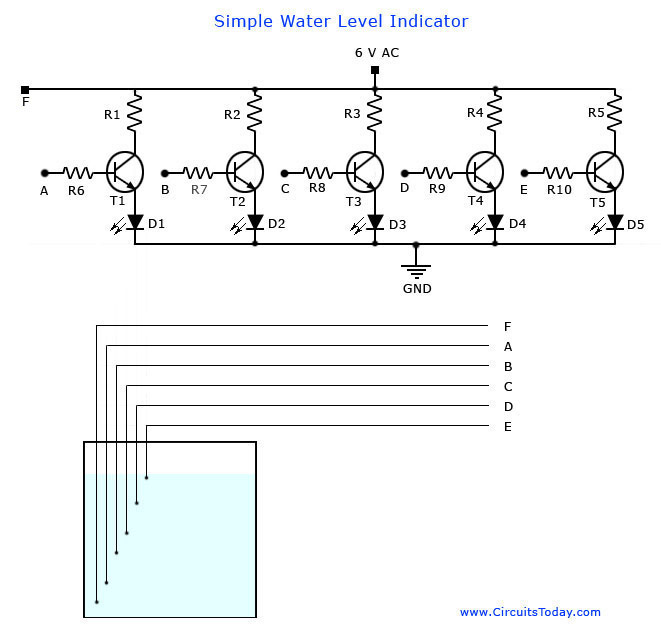
A simple water level indicator project with a circuit diagram for home and industry. This water tank level sensor can be utilized for any liquid level indicator projects. The water level indicator circuit is designed to monitor and display the...
A battery-status indicator circuit is useful for monitoring portable test equipment and similar devices. LED D1 flashes to attract the user's attention, signaling that the circuit is operational, preventing it from being left on unintentionally. The circuit produces approximately...
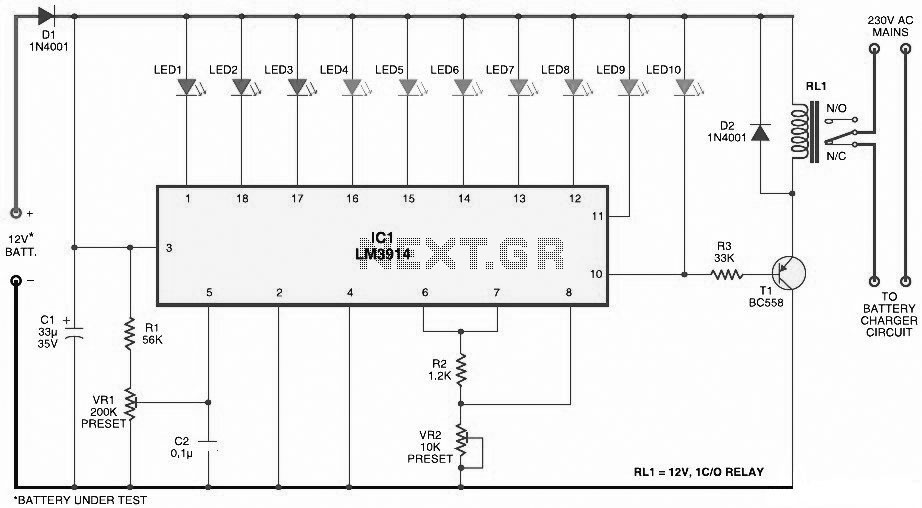
This document presents a circuit diagram for a simple and easy-to-construct battery level indicator. Typically, in mobile phones, battery levels are shown in either dot or bar format, allowing users to easily recognize the battery status. The battery level indicator...
The headlights of a 2001 Chevy S10 sometimes function and sometimes do not, along with the dashboard indicator light. All other lights are operational. The headlight switch, fuse, and relay have been replaced, and the headlight bulbs have been...