
Blinking an LED AVR Tutorial

The circuit design for the blinking LED project is straightforward yet essential for understanding microcontroller operation. The schematic includes an AVR microcontroller, an LED, a 470-ohm resistor, and a power supply. The LED is connected to pin PB0 of the AVR, while the resistor is placed in series with the LED to limit the current flowing through it, ensuring it operates within safe parameters. The configuration of the microcontroller is crucial, as it must be programmed to set the PB0 pin as an output and toggle its state at defined intervals, creating the blinking effect. The power supply must deliver a stable +5V to the microcontroller to ensure reliable operation. Various power supply options are available, each with its advantages, allowing flexibility based on the project requirements and available resources. Proper understanding of the microcontroller's pin configuration and the function of each component in the circuit is vital for successful implementation and troubleshooting.Blinking an LED is the " Hello World " of programming microcontrollers. It is a great way to work through the entire development process and make sure all your tools are in working order. In this chapter you will wire up a light emitting diode (LED) to an AVR on a breadboard, write a C program to blink that LED, and then program that code into the
AVR. The following items are needed to complete the Blink LED project. Links are provided to purchase the items at Jameco Electronics. See the Tools & Equipment section for a general list of items used throughout this tutorial series. If you have a AVR microcontroller that has been previously used then it`s "fuse bits" may have been modified. You will need to restore it`s fuses to factory defaults to complete this tutorial. If you are not familiar with wiring integrated circuits (ICs), the AVR chip have a little notch at one end to designate the "top".
The pin numbering starts at 1 on the top left, progress squentially down the left side, and then back up the right side as shown in the schematic above. A 470 resistor (R2) and an LED (LED1) are connected to pin PB0. The resistor is a "current limiting" resistor to limit the current (mA) passing through the LED so that it doesn`t burn out.
When PB0 goes low (0V) the LED will turn on. When PB0 goes high (+5V) the LED turns off. The schematic shows a DC power source of +5V to power the microcontroller, however, it`s up to you to provide that +5V. One of the most common ways hobbyists use provide +5V to projects is to use a 9V battery with a 7805 voltage regulator IC to drop the voltage down to +5V.
I prefer to use 4 rechargable AA batteries (4 batteries x 1. 2V ea. = 4. 8V). You can pick up rechargable AA batteries and chargers just about anywhere these days. You can wire them up to you breadboard using a 4-AA Battery Holder along with a 9V Battery Clip as shown in figure 2. 3. Of course, having a +5V power source in your "lab" (whatever that may be) is invaluable. Hobbyists often get +5V out of a wall outlet by using an expensive lab power supply (which is awesome if you can afford it), using a +5V AC/DC wall adaptor, using the +5V line of an ATX computer power supply, or tapping the +5V line from a USB bus or USB charger.
The C program must be compiled into an Intel HEX formated file. This is the format that is passed to avrdude which tells the AVR programmer what to program into the microcontroller. The HEX file is created in two steps. First, avr-gcc will be used to compile the C program blink. c into a binary ELF (Executable and Linkable Format) object file. This new file will be named blink. elf. -mmcu, tells the compiler which AVR microcontroller the code is being compiled for. If you are not using an ATmega328P then you will need to change it to the AVR that you are using. -Wall turns on all reasonable compiler warnings which will help make sure you`re writing good code. Any time you see a warning you will want to investigate what it means. -j specifies Memory Sections to copy from the ELF file. It is used twice, once to copy the. text section and once for the. data sections. The. text section contains the machine instructions which make up the program. The. data section contains various static data used in the program. As was described in Overview of the Development Process, the "firmware" which tells the AVR microcontroller what to do is written in C.
The GNU Toolchain is used to compile that code into a file formatted for programming into the AVR. This code configures the PB0 pin on the AVR microcontroller as a digital output. Then, it toggles the state of that pin every 500 ms. For now, just copy and paste this code into a file named blink. c. Now for the moment of truth. The blink. hex file will now be programmed into the microcontroller using the avrdude program. Make sure the AVR programmer is connected to your circuit and to your computer and that the circuit 🔗 External reference
Related Circuits

This project Digital gated Emulator using Microcontroller is used to emulate the basic gates such us NOT, OR, AND. The system has the selector switch by which we can select any gate. The system has two inputs and one...

The circuit diagram for an electric start and stop timer is illustrated in the following cycle. It utilizes the LM555 integrated circuit configured as an adjustable duty cycle multivibrator. The circuit includes components C3, KH1, W1, KH2, and W2,...

The incandescent light bulb has been the leading choice for lighting applications since its introduction in the late 19th century; however, its efficiency has consistently remained below five percent. Growing global ecological awareness and the demand for more cost-effective...
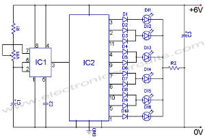
The following circuit illustrates an LED Knight Rider Circuit Diagram. This circuit is based on the 4017 and 555 integrated circuits. Features include the Knight Rider effect with four LEDs. The LED Knight Rider circuit is designed to create a...
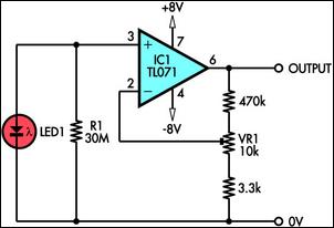
This circuit demonstrates the use of a standard LED as a light sensor by utilizing the photovoltaic voltage generated across the LED when it is exposed to light. LEDs are cost-effective alternatives to photodiodes and include a built-in filter...
A 10 bit scanning voltmeter with a Minimum Mass Wireless Coupler, based on the ATMega8. Range to the Minimum Mass Base Unit is 10 to 15 cm. If the voltmeter is battery operated, it can be floated from ground....